


LM1035 36 application circuit
#LM1035
#loudness compensation
#bass boost
#audio control
#DC voltage
#sound enhancement
#audio processing
#equalization
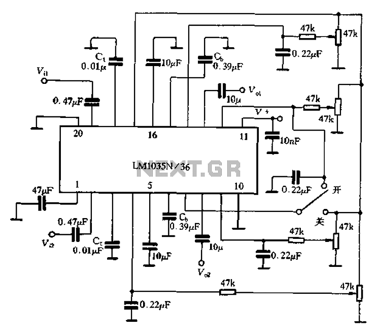
Description: The circuit includes a loudness compensation control terminal at pin 7, which, when combined with the DC control voltage, forms a simple loudness compensation mechanism that enhances bass response. When the loudness control switch is in the OFF position, pins 7 and 17 are connected, resulting in a voltage of 4V at pin V7-5, and the loudness compensation feature is disabled. Conversely, when the control switch is in the ON position, pins 7 and 12 connect, enabling the loudness compensation functionality. Adjustments to the loudness compensation characteristics can be made by changing the capacitance of capacitors Ct or Cb or by altering the voltage at pin 7. Pins 3 and 18 serve as external terminals for a two-channel treble control capacitor, while pin 615 functions as the external terminal for a two-channel bass control capacitor.
The loudness compensation circuit is designed to enhance audio playback by boosting lower frequency sounds, which can be particularly beneficial when listening at lower volumes. The circuit operates based on a straightforward switching mechanism that connects different pins depending on the desired state of the loudness compensation feature.
In the OFF state, the connection between pins 7 and 17 ensures that the circuit does not engage the loudness compensation, maintaining a flat frequency response. The 4V at pin V7-5 indicates that the circuit is effectively bypassed, allowing for standard audio output without any alteration to the bass frequencies.
When the loudness control is activated (ON position), the connection shifts to pins 7 and 12, which engages the loudness compensation function. This activation allows the circuit to process the audio signal differently, enhancing the bass frequencies to provide a richer sound experience. The adjustment of capacitors Ct and Cb is crucial for tailoring the loudness characteristics to the specific requirements of the audio system, allowing for fine-tuning based on user preference or room acoustics.
Additionally, the external treble control capacitor connected to pins 3 and 18 provides flexibility in managing high-frequency response, enabling users to adjust treble levels independently of the loudness compensation. Similarly, the external bass control capacitor at pin 615 allows for further customization of low-frequency response, ensuring that the sound output can be optimized for various listening environments or personal preferences.
Overall, this circuit configuration provides a versatile solution for enhancing audio playback, allowing for both loudness compensation and independent control over treble and bass frequencies.7 feet for loudness compensation control terminal, the foot plus the DC control voltage can be composed of simple loudness compensation, was obtained additional high bass boost . When loudness control switch in the off position (Figure 4-22), 7 feet and 17 feet in contact, then V7-5 4V, loudness compensation does not work; When the control switch in the ON position 7 feet and 12 feet in contact, the availability of loudness compensation. Change Ct or Cb capacity or changing the voltage of 7 feet, can be adjusted loudness compensation characteristics.
3,18 feet are two-channel external treble control capacitor C external terminal; 615 feet are two-channel external bass control capacitor CI) external end.
The loudness compensation circuit is designed to enhance audio playback by boosting lower frequency sounds, which can be particularly beneficial when listening at lower volumes. The circuit operates based on a straightforward switching mechanism that connects different pins depending on the desired state of the loudness compensation feature.
In the OFF state, the connection between pins 7 and 17 ensures that the circuit does not engage the loudness compensation, maintaining a flat frequency response. The 4V at pin V7-5 indicates that the circuit is effectively bypassed, allowing for standard audio output without any alteration to the bass frequencies.
When the loudness control is activated (ON position), the connection shifts to pins 7 and 12, which engages the loudness compensation function. This activation allows the circuit to process the audio signal differently, enhancing the bass frequencies to provide a richer sound experience. The adjustment of capacitors Ct and Cb is crucial for tailoring the loudness characteristics to the specific requirements of the audio system, allowing for fine-tuning based on user preference or room acoustics.
Additionally, the external treble control capacitor connected to pins 3 and 18 provides flexibility in managing high-frequency response, enabling users to adjust treble levels independently of the loudness compensation. Similarly, the external bass control capacitor at pin 615 allows for further customization of low-frequency response, ensuring that the sound output can be optimized for various listening environments or personal preferences.
Overall, this circuit configuration provides a versatile solution for enhancing audio playback, allowing for both loudness compensation and independent control over treble and bass frequencies.7 feet for loudness compensation control terminal, the foot plus the DC control voltage can be composed of simple loudness compensation, was obtained additional high bass boost . When loudness control switch in the off position (Figure 4-22), 7 feet and 17 feet in contact, then V7-5 4V, loudness compensation does not work; When the control switch in the ON position 7 feet and 12 feet in contact, the availability of loudness compensation. Change Ct or Cb capacity or changing the voltage of 7 feet, can be adjusted loudness compensation characteristics.
3,18 feet are two-channel external treble control capacitor C external terminal; 615 feet are two-channel external bass control capacitor CI) external end.
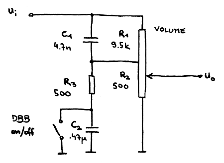
Dynamic Bass Boost
Some time ago, repairs were conducted on a Philips portable radio/CD/cassette player, which featured a sticker indicating the presence of Dynamic Bass Boost. This feature is essentially an additional switch that alters the audio output when activated. It serves as...
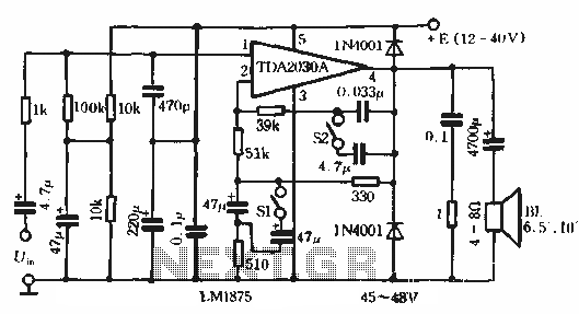
Bass Boost amplifier circuit with compensation
This circuit features bass boost compensation for a practical power amplifier. It is important to adhere to the specified parameters of the amplifier circuit elements. When switches S1 and S2 are disconnected, the bass boost function can be set to...
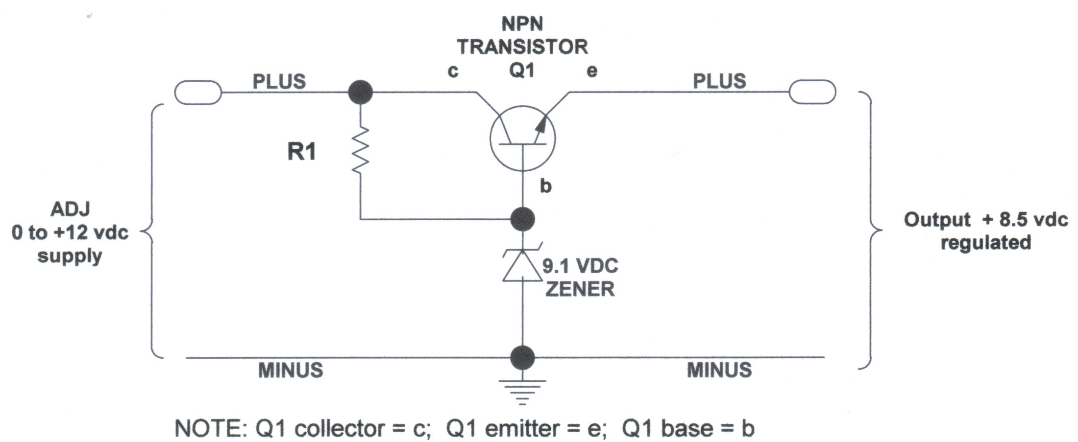
voltage regulators
DC Voltage Regulator (NPN & Zener Regulator) There are instances where it is handy to have a regulated DC voltage power supply for use on your model.
A DC voltage regulator is an essential component in electronic circuits that provides a...
The second equalization circuit
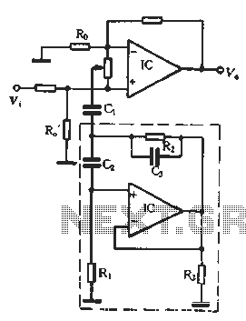
In the second equalization circuit connection method, it operates as illustrated in Figure 1-96. When the potentiometer wiper is moved to the inverting input terminal "a", the resonance impedance of the parallel combination of the feedback resistor RB reaches its...
ARRL Handbook Audio Intelligibility Enhancer
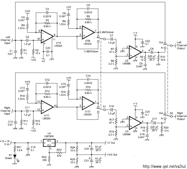
Assistance is sought for building the N4GG audio intelligibility enhancer project as detailed in the ARRL Handbook. A circuit board has been ordered from Far Circuits, but there are difficulties in sourcing the necessary components. Attempts have been made to...
Audio Beat Detect ?« Electronic Product Design
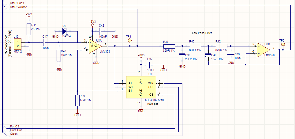
This circuit employs a digital potentiometer to enable the microcontroller to automatically adjust the circuit's gain according to the ambient audio volume. However, a standard potentiometer can be used if automatic adjustment is unnecessary. The low-pass filter design is based...
ld168 audio control circuit diagram of a voltage-controlled flash decoration
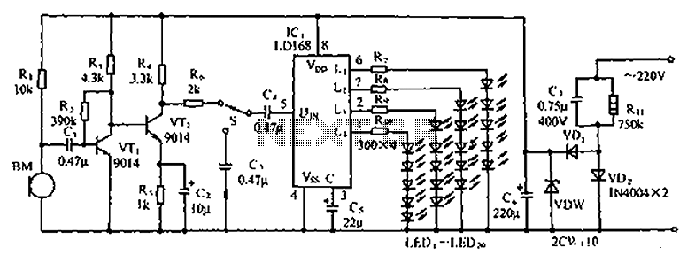
The circuit depicted in the figure involves the LD168, which functions as a sound level indicator for tape recorder speakers. It features four outputs capable of directly driving multiple light-emitting diodes. Additionally, the device can be activated by a thyristor...
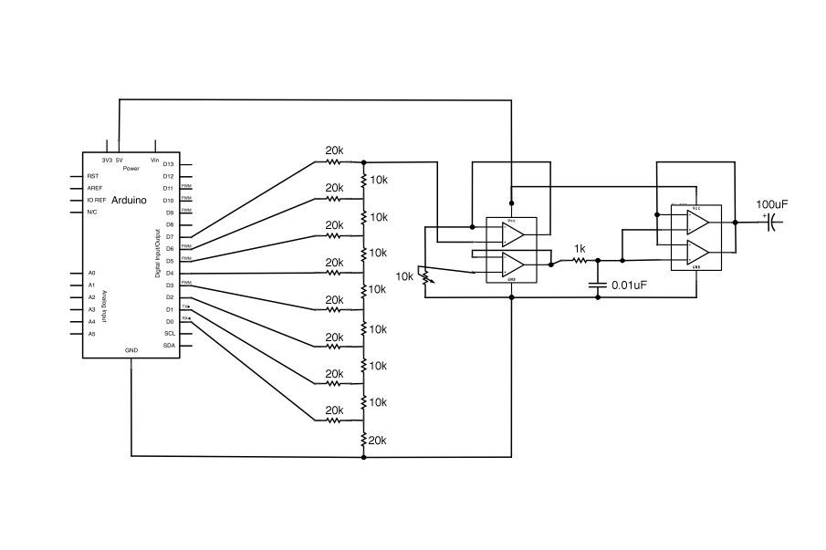
Arduino Vocal Effects Box
This Arduino-powered vocal effects box pitch shifts and distorts incoming audio signals to produce a wide variety of vocal effects. This project is an experiment with real-time digital signal processing using Arduino. It samples an incoming microphone signal at a...
The second equalization circuit
In the second equalization circuit connection method, it operates as illustrated in Figure 1-96. When the potentiometer wiper is moved to the inverting input terminal "a", the resonance impedance of the parallel combination of the feedback resistor RB reaches its...