


Overview of 2.1 (Satellite/Subwoofer) Speaker Systems
#speaker system
#subwoofer
#power amplifier
#audio amplifier
#5V power supply
#satellite speakers
#2.1 system
#audio output
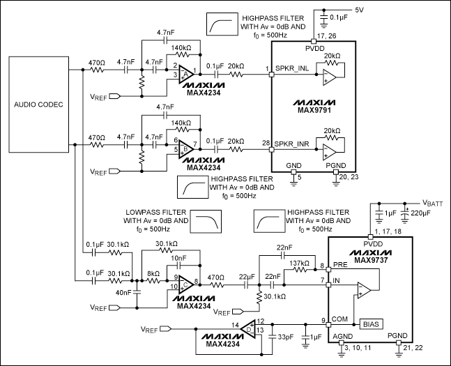
Description: This application note explains how to implement a 2.1 (satellite/subwoofer) audio power-amplifier system with 2 x 2W and 1 x 7W of output power from a single 5V power supply.
The described 2.1 audio power-amplifier system is designed to deliver a total output of 11 watts, effectively distributing audio signals across two satellite speakers and one subwoofer. The system utilizes a single 5V power supply, which simplifies the design and enhances efficiency by minimizing power loss.
The architecture of the amplifier system typically comprises two separate channels for the satellite speakers, each capable of delivering 2 watts of output, and one channel dedicated to the subwoofer, which provides 7 watts of output power. The choice of a 5V power supply is advantageous as it is commonly available and easily integrated into various applications, including portable and battery-operated devices.
The amplifier circuit can be built using integrated circuits that are optimized for low-voltage operation. For the satellite channels, Class-D amplifier ICs are often employed due to their high efficiency and compact size. These amplifiers convert the input audio signal into a pulse-width modulated (PWM) signal, which is then used to drive the speakers with minimal heat generation.
For the subwoofer channel, a more powerful amplifier capable of handling the increased output is necessary. This may involve a dedicated Class-D or Class-AB amplifier, depending on the desired audio fidelity and efficiency. The circuit design should include appropriate filtering components, such as inductors and capacitors, to ensure that the audio signals are clean and free of distortion.
In addition to the amplifier circuits, the design may also incorporate a crossover network to manage the frequency distribution between the satellite speakers and the subwoofer. This network ensures that the subwoofer only receives low-frequency signals, while the satellite speakers handle mid to high frequencies, resulting in a balanced audio output.
Overall, the implementation of a 2.1 audio power-amplifier system with the specified output power from a single 5V power supply is a practical solution for enhancing audio performance in compact electronic devices. The careful selection of components and circuit design will significantly influence the system's overall sound quality and efficiency.Application note explains how to implement a 2.1 (satellite/subwoofer) audio power-amplifier system with 2 x 2W and 1 x 7W of output power from a single 5V power supply..
The described 2.1 audio power-amplifier system is designed to deliver a total output of 11 watts, effectively distributing audio signals across two satellite speakers and one subwoofer. The system utilizes a single 5V power supply, which simplifies the design and enhances efficiency by minimizing power loss.
The architecture of the amplifier system typically comprises two separate channels for the satellite speakers, each capable of delivering 2 watts of output, and one channel dedicated to the subwoofer, which provides 7 watts of output power. The choice of a 5V power supply is advantageous as it is commonly available and easily integrated into various applications, including portable and battery-operated devices.
The amplifier circuit can be built using integrated circuits that are optimized for low-voltage operation. For the satellite channels, Class-D amplifier ICs are often employed due to their high efficiency and compact size. These amplifiers convert the input audio signal into a pulse-width modulated (PWM) signal, which is then used to drive the speakers with minimal heat generation.
For the subwoofer channel, a more powerful amplifier capable of handling the increased output is necessary. This may involve a dedicated Class-D or Class-AB amplifier, depending on the desired audio fidelity and efficiency. The circuit design should include appropriate filtering components, such as inductors and capacitors, to ensure that the audio signals are clean and free of distortion.
In addition to the amplifier circuits, the design may also incorporate a crossover network to manage the frequency distribution between the satellite speakers and the subwoofer. This network ensures that the subwoofer only receives low-frequency signals, while the satellite speakers handle mid to high frequencies, resulting in a balanced audio output.
Overall, the implementation of a 2.1 audio power-amplifier system with the specified output power from a single 5V power supply is a practical solution for enhancing audio performance in compact electronic devices. The careful selection of components and circuit design will significantly influence the system's overall sound quality and efficiency.Application note explains how to implement a 2.1 (satellite/subwoofer) audio power-amplifier system with 2 x 2W and 1 x 7W of output power from a single 5V power supply..
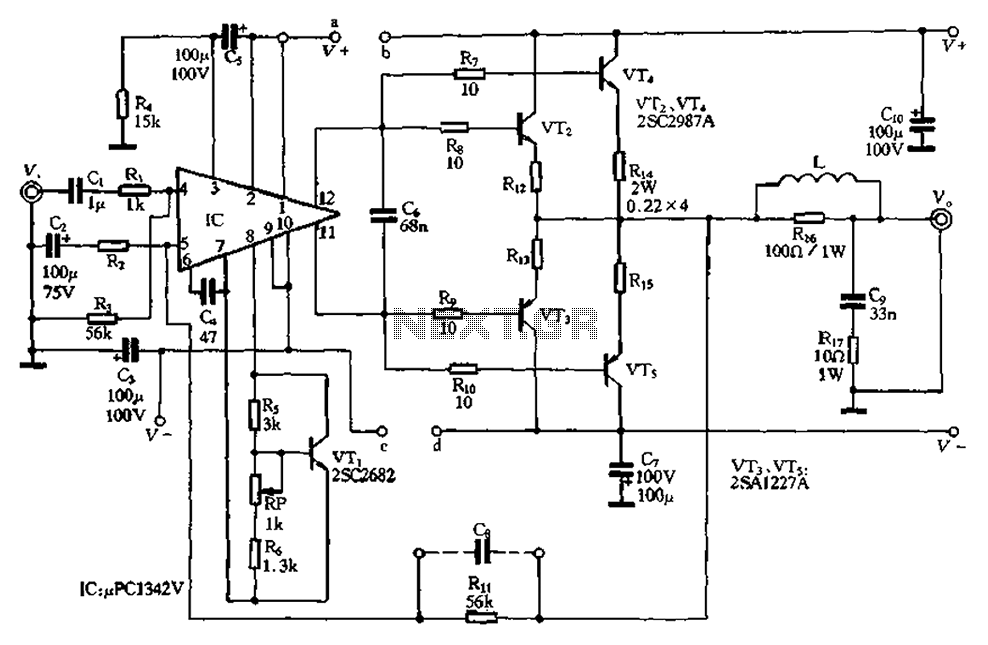
Compact 100W power amplifier circuit
The pLPC1342V and NE are two companies involved in a tube amplifier circuit utilizing 2SA1227A and 2SC2987A transistors, achieving a maximum output power of up to 120W with a cutoff frequency of up to 500 MHz. The circuit, illustrated in...
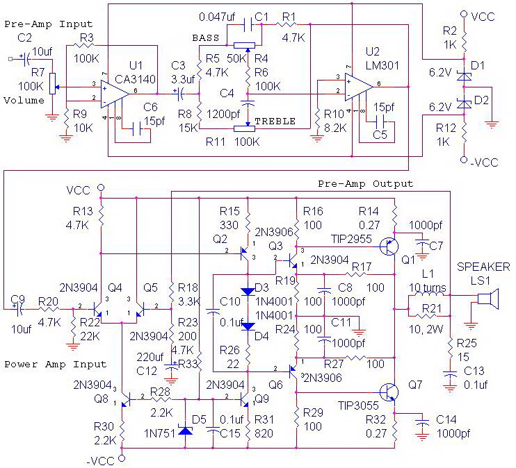
complete 70 watt power amplifier schematic
The circuit power amplifier depicted is a schematic design for a power amplifier with an output power of 70 watts, operating in Class AB mode. This power amplifier circuit is equipped with a tone control circuit. The 70-watt power amplifier...
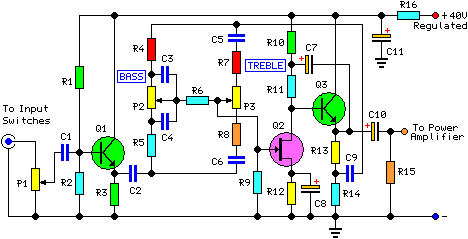
30 Watt Audio Power Amplifier
This project involved the design of an audio amplifier capable of delivering substantial output power with minimal component count while maintaining high quality. The power amplifier section utilizes three transistors along with a few resistors and capacitors in a shunt...
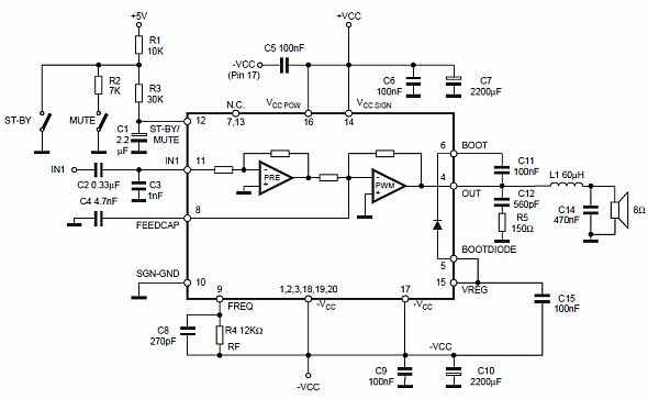
10W Class D Power Audio Amplifier with TDA7480
Class D audio power amplifier schematic diagram with TDA7480, capable of 10W output power at a load of 8Ω/4Ω and a total harmonic distortion of 10%. Requires a split-supply (max. ±20V).
The Class D audio power amplifier utilizing the TDA7480 is...
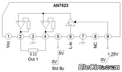
Audio amplifier with IC AN7522 AN7523 and TDA2616
The third series of the function utilizes the same system, specifically BTL (Bridge Transformer Less). This configuration offers several advantages, including the elimination of coupling capacitors and coupling transformers.
The BTL (Bridge Transformer Less) configuration is a significant advancement in audio...
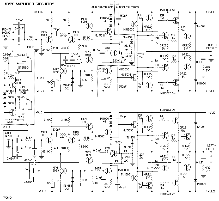
Power Amplifiers
It is important to note that there is limited protection circuitry and fuses in this amplifier. A short turn-on delay for the output power supply is included to minimize thumps, along with a couple of line fuses, but no additional...
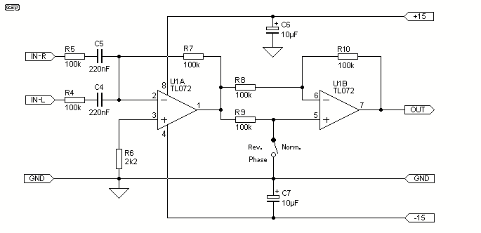
Subwoofer Equaliser
The Linkwitz transform circuit (or EAS principle) will allow any driver to extend to 20 Hz or even lower. A good quick test is to stick the speaker in a box, and drive it to 50 or 100W or so...
8W Audio Amplifier
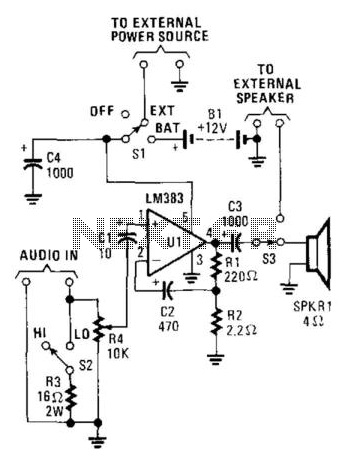
This audio power amplifier, built around an LM383 8-W audio power amplifier, is designed to enhance an audio signal to a sufficient level for audibility in high-noise environments. It is important to note that the LM383 requires a heatsink for...
Subwoofer Filter Circuit Using Op-Amp TL072
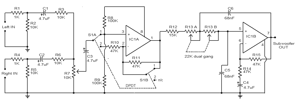
This is a simple subwoofer filter circuit that can be powered by a 12V DC source. It is particularly useful in automotive applications for subwoofers. The circuit functions as a low-pass filter, with a pass frequency adjustable between 60 Hz...