


Simple Easy Parametric and Graphic EQs Plus Peaks and Notches
#equalizer
#wah pedal
#resonant peak
#notch filter
#parametric EQ
#graphic EQ
#sound shaping
#audio processing
#frequency control
#music effects
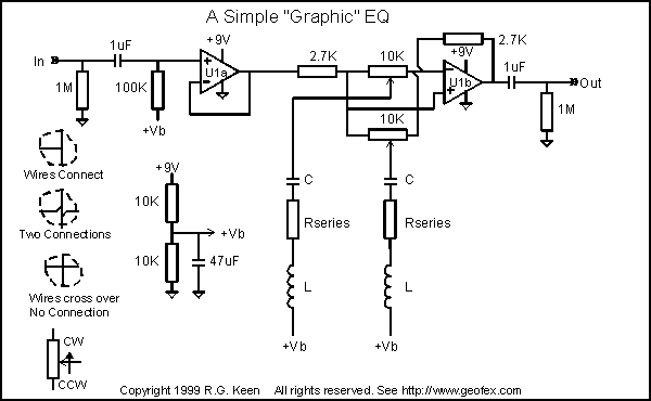
Description: The sound of a wah pedal is characterized by a resonant peak in the signal that can be adjusted. In contrast, a notch represents a sudden decrease in level at a specific frequency, which can be advantageous for achieving particular sounds. An ideal scenario would allow for the selection of either a peak or a notch based on control settings. The frequency response diagram illustrates the potential responses of a variable Q peak/notch filter. The term "Q" refers to the ratio of energy stored to energy dissipated per cycle within a network. For practical understanding, a guitar string, when plucked, vibrates for an extended period due to the energy stored during the initial motion, which dissipates minimally per cycle, indicating a high Q mechanical filter. Conversely, applying pressure to the string dampens its vibration, lowering its Q by removing energy with each oscillation. Q also measures bandwidth; it can be calculated by dividing the center frequency of a filter's response by the frequency difference where the response is half of the center response. A moderately resonant filter, similar to a wah pedal, exhibits a peak in frequency response at its resonant frequency, typically within a Q range of 2-10. A high Q filter, analogous to a guitar string, vibrates primarily at a single frequency, while a lower Q results in a broader resonance. A high Q notch filter operates similarly to a high Q peaking filter but creates a dead zone with minimal signal response at the notch frequency. Higher Q notches result in a more pronounced cut at the notch frequency with a narrower frequency band affected, while lower Q notches affect a wider frequency range to a lesser degree. For an advanced tone control system, the goal is to adjust both the peak/notch depth and its frequency location. The circuit design resembles a simplified high-fidelity graphic equalizer, featuring multiple series L-C filters connected to potentiometer wipers, one for each L-C filter. Series LC filters exhibit high impedance except at their resonant frequency, where the impedance drops to a minimum, ideally zero in perfect components. The resonant frequency can be calculated using the formula Fr = 1/(2*pi*SQRT(L*C)). When the potentiometer wiper is set to the input side, it grounds the input through the low impedance of the LC filter at that frequency, creating a notch in the frequency response. If adjusted to the inverting input, it shunts feedback to ground at the resonant frequency, generating a peak response. When positioned centrally, the LC filter has no effect, resulting in a flat frequency response.
The described circuit employs a variable Q peak/notch filter, which is an essential component in audio processing, particularly in musical applications. The variable Q characteristic allows for dynamic manipulation of the sound, providing musicians and audio engineers with the ability to shape tone and timbre effectively. The use of series L-C filters ensures that the circuit can selectively attenuate or boost specific frequency ranges, facilitating creative sound design.
In practical applications, the design can be implemented using operational amplifiers configured for inverting and non-inverting operations, allowing for precise control over gain and phase characteristics. The potentiometers serve as variable resistors, enabling real-time adjustments to the filter's response, thus enhancing the user's ability to tailor the sound to their preferences.
The circuit can be further enhanced by incorporating additional features such as LED indicators to visualize the active frequency range, or by integrating digital control systems for automated adjustments. The potential for modular designs also exists, allowing for the integration of various filter types or configurations to expand the tonal palette available to the user. Overall, the variable Q peak/notch filter circuit represents a versatile tool in sound engineering, offering significant flexibility in audio manipulation.Everyone is familiar with the sound of a wah pedal. This is a resonant peak in the signal that can get moved around. Not so familiar is a notch, or a sudden reduction in level at one frequency. Sometimes a notch can be very useful in getting a specific sound. Even better would be if you could get either a peak or a notch, depending on how you set the controls - something like the frequency response diagram. The diagram shows the possible frequency responses of a variable Q peak/notch filter. "Wait a minute! What`s Q " I hear you ask. The techie explanation is that Q is the energy stored divided by the energy dissipated per cycle in a network. Let me translate that into something more useful. A guitar string will vibrate a long time if plucked. The initial pluck that sets it into motion stores a chunk of energy in the string that is saved by the interchange of motion for string stretch on every vibration.
It dissipates very little of its energy per cycle, so it stays in motion a long time - it`s a high Q mechanical filter. If you put your finger on the string, it stops ringing very quickly because your finger damps it, removing a lot of energy as the string moves.
Your finger has lowered the Q of the vibrating string, removing a lot of energy from it each vibration, so it stops vibrating quickly. Q is also a measurement of bandwidth. Another engineer`s measurement of Q is to divide the center frequency of the filter`s response by the difference between the frequencies where the response is 1/2 of the center response.
Q is kind of a measurement of resonance, then. A moderately resonant filter is like a wah pedal - There is a peak of frequency response at the resonant frequency of the wah. To give you an idea about how Q relates to sound, most wahs have a Q of about 2-10. Q is also related to selectivity. A high Q filter, like a guitar string, vibrates primarily at one frequency. As Q gets lower, the resonance gets wider in frequency. A high Q notch is just like the reverse of a high Q peaking filter. A notch filter has a kind of a dead zone where there is very little or no response to signal - very much like a guitar string with a dead or muffled note on one fret.
The higher the Q of a notch filter, the more the response is cut at the notch frequency and the narrower the band of frequencies that are cut. Low Q notches cut a broader band of frequencies by a lesser amount. For our super-variable tone control, we`d like to not only have the peak/notch depth adjustable, we`d like to move it around in frequency, like the sketch at the right shows.
The circuit is a simplified version of a hifi graphic EQ. There are a number of series L-C filters which are connected to the wipers of a pot, one per L-C filter. It is a characteristic of a series LC filter that it has a high impedance except at its resonant frequency.
At that frequency, the series impedance drops to a minimum, which is zero if the components are perfect. The resonant frequency may be calculated as Fr=1/(2*pi*SQRT(L*C). Effectively, the wiper of each pot is grounded through the low impedance of the LC filter at that frequency.
The pot wiper may be dialed to the input side, in which case it shunts the input to ground, producing a notch in the frequency response at its center frequency. It may also be dialed to the inverting input, which shunts the feedback to ground at its resonant frequency, producing a peak when directly in the center, there is no effect from the LC filter at all - frequency response is flat.
In this position, the LC filter`s eff
The described circuit employs a variable Q peak/notch filter, which is an essential component in audio processing, particularly in musical applications. The variable Q characteristic allows for dynamic manipulation of the sound, providing musicians and audio engineers with the ability to shape tone and timbre effectively. The use of series L-C filters ensures that the circuit can selectively attenuate or boost specific frequency ranges, facilitating creative sound design.
In practical applications, the design can be implemented using operational amplifiers configured for inverting and non-inverting operations, allowing for precise control over gain and phase characteristics. The potentiometers serve as variable resistors, enabling real-time adjustments to the filter's response, thus enhancing the user's ability to tailor the sound to their preferences.
The circuit can be further enhanced by incorporating additional features such as LED indicators to visualize the active frequency range, or by integrating digital control systems for automated adjustments. The potential for modular designs also exists, allowing for the integration of various filter types or configurations to expand the tonal palette available to the user. Overall, the variable Q peak/notch filter circuit represents a versatile tool in sound engineering, offering significant flexibility in audio manipulation.Everyone is familiar with the sound of a wah pedal. This is a resonant peak in the signal that can get moved around. Not so familiar is a notch, or a sudden reduction in level at one frequency. Sometimes a notch can be very useful in getting a specific sound. Even better would be if you could get either a peak or a notch, depending on how you set the controls - something like the frequency response diagram. The diagram shows the possible frequency responses of a variable Q peak/notch filter. "Wait a minute! What`s Q " I hear you ask. The techie explanation is that Q is the energy stored divided by the energy dissipated per cycle in a network. Let me translate that into something more useful. A guitar string will vibrate a long time if plucked. The initial pluck that sets it into motion stores a chunk of energy in the string that is saved by the interchange of motion for string stretch on every vibration.
It dissipates very little of its energy per cycle, so it stays in motion a long time - it`s a high Q mechanical filter. If you put your finger on the string, it stops ringing very quickly because your finger damps it, removing a lot of energy as the string moves.
Your finger has lowered the Q of the vibrating string, removing a lot of energy from it each vibration, so it stops vibrating quickly. Q is also a measurement of bandwidth. Another engineer`s measurement of Q is to divide the center frequency of the filter`s response by the difference between the frequencies where the response is 1/2 of the center response.
Q is kind of a measurement of resonance, then. A moderately resonant filter is like a wah pedal - There is a peak of frequency response at the resonant frequency of the wah. To give you an idea about how Q relates to sound, most wahs have a Q of about 2-10. Q is also related to selectivity. A high Q filter, like a guitar string, vibrates primarily at one frequency. As Q gets lower, the resonance gets wider in frequency. A high Q notch is just like the reverse of a high Q peaking filter. A notch filter has a kind of a dead zone where there is very little or no response to signal - very much like a guitar string with a dead or muffled note on one fret.
The higher the Q of a notch filter, the more the response is cut at the notch frequency and the narrower the band of frequencies that are cut. Low Q notches cut a broader band of frequencies by a lesser amount. For our super-variable tone control, we`d like to not only have the peak/notch depth adjustable, we`d like to move it around in frequency, like the sketch at the right shows.
The circuit is a simplified version of a hifi graphic EQ. There are a number of series L-C filters which are connected to the wipers of a pot, one per L-C filter. It is a characteristic of a series LC filter that it has a high impedance except at its resonant frequency.
At that frequency, the series impedance drops to a minimum, which is zero if the components are perfect. The resonant frequency may be calculated as Fr=1/(2*pi*SQRT(L*C). Effectively, the wiper of each pot is grounded through the low impedance of the LC filter at that frequency.
The pot wiper may be dialed to the input side, in which case it shunts the input to ground, producing a notch in the frequency response at its center frequency. It may also be dialed to the inverting input, which shunts the feedback to ground at its resonant frequency, producing a peak when directly in the center, there is no effect from the LC filter at all - frequency response is flat.
In this position, the LC filter`s eff
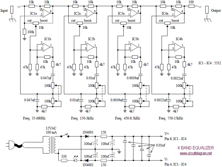
4 Band Equalizer schematic diagram
The following diagram illustrates a four-band blaster circuit. This blaster is utilized to enhance sound fidelity, emphasize specific instruments, eliminate unwanted noise, or create entirely new and distinct timbres.
The four-band blaster circuit is designed to manipulate audio signals across four...
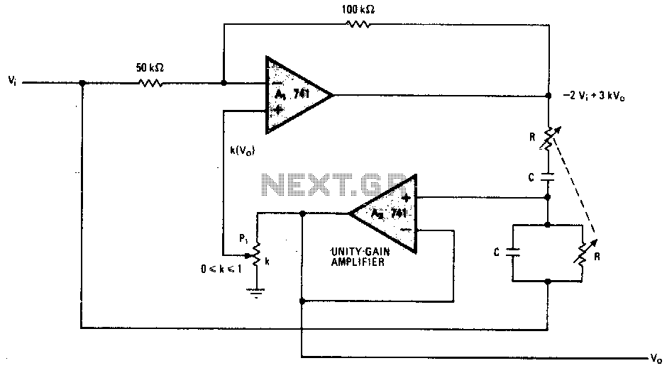
Selectable bandwidth notch filter
This notch filter operates at frequencies up to 200 kHz and utilizes a modified Wien bridge to select the center frequency. The PI component determines the notch bandwidth, which defines the range of frequencies that are attenuated. The notch depth...
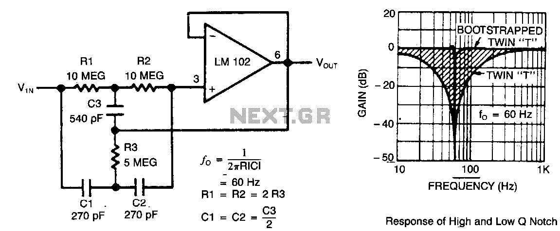
High-q-notch-filter
This circuit illustrates a twin-T network connected to an LM102 to form a high-Q, 60-Hz notch filter. The junction of R3 and C3, which is typically grounded, is bootstrapped to the output of the follower. Due to the low output...
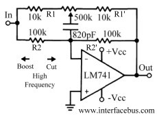
Audio Equalizer Circuits
This discussion continues from the audio tone control topic, which introduced both passive and active tone controls. The follow-up topics may include a 2-Band Active Tone Control or a 3-Band Active Tone Control. An audio equalizer is utilized to adjust...
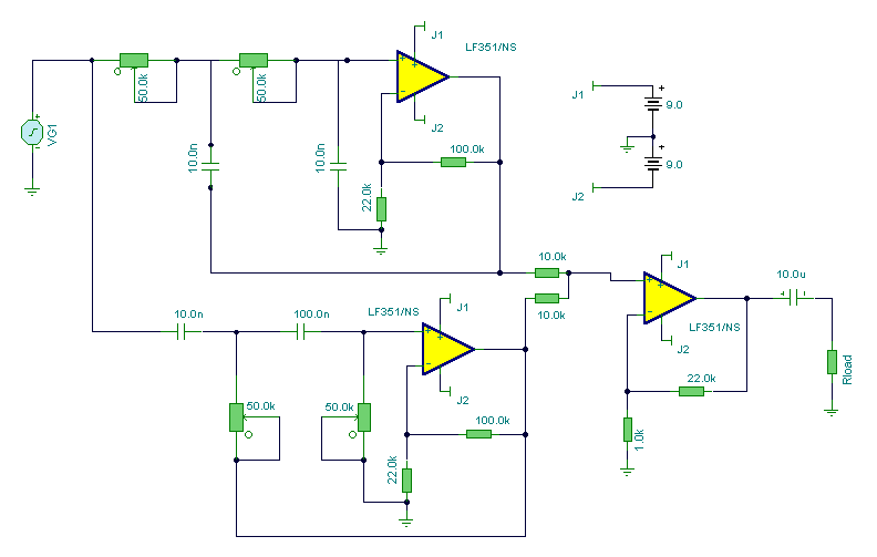
Notch Filter
At first glance, this circuit appears to be quite complex; however, it can be segmented into high-pass and low-pass filter sections, followed by a summing amplifier with a gain of approximately 20 times. The supply rail voltage is +/- 9V...
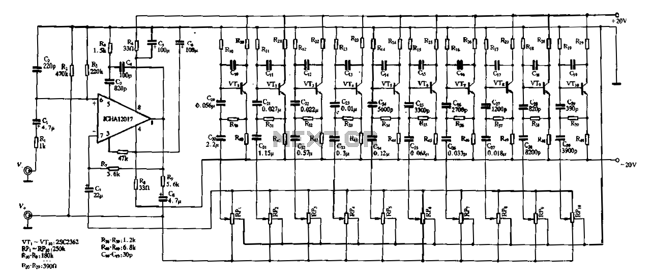
Ten-segment frequency equalizer
Figure 1-97 illustrates a ten-band equalizer circuit with its initial connection. Figure 1C represents the utility voltage amplifier, with R7 functioning similarly to the island depicted in Figure 1-92 R1. Additionally, R2 and the transistors VTr to VTio form the...
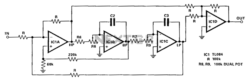
Audio notch filter 2
The circuit illustrated here demonstrates that the response at one octave off-tune remains within 10% of the far-out response. The sharpness of the notch can be adjusted by increasing or decreasing the 68-ohm resistor. The linearity tracking of resistors R8...
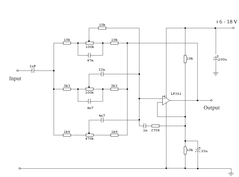
Equalizer Circuit Operating on Three Bands
The circuit was designed to illustrate the use of a tone control circuit, which adjusts audio signals before they are sent to any output device.
The tone control circuit serves as an essential component in audio processing systems, allowing for the...
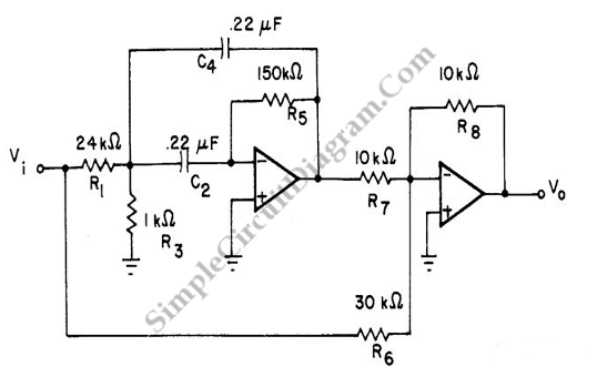
Two Op-Amps 60 Hz Notch Filter
A notch filter is a type of filter designed to eliminate a specific frequency component. Ideally, a notch filter targets a single frequency point; however, in practice, it may affect a range of frequencies around the target.
A notch filter, also...