


Single Chip Theremin Circuit
#Theremin
#Colpitts oscillator
#LC oscillator
#beat frequency
#electronic music
#frequency control
#hand movement sensor
#audio synthesis
#music instrument
#rectifier

Description: This schematic diagram illustrates a single-chip Theremin circuit. A Theremin is an electronic musical instrument that detects hand movements to control tones and frequency. The circuit employs two separate Colpitts LC oscillators to generate a beat frequency. The frequencies of the two Colpitts LC oscillators are mixed and subsequently rectified. This rectification demodulates the mixed signal to obtain the beat frequency, which falls within the audible range. The resulting beat frequency, or difference, serves as the true output of the Theremin. The oscillators operate at high frequencies (inaudible) to achieve a broad audible frequency range for the beat frequency when the outputs of the two oscillators are combined. This circuit utilizes a 4011 quad gate to construct a high-frequency oscillator functioning at 250 kHz. The metal probe used to sense hand movements produces only a minor frequency shift relative to the original frequency; therefore, deriving the beat frequency is essential for achieving a wide audible frequency range as a result of high-frequency shifting. The IC2, an LM741, amplifies the mixed signal before rectification. The diode D1 rectifies the mixed signal to extract the audio (the beat frequency). This audio signal is then filtered by an adjustable bandpass filter, IC3. Further audio amplification, prior to the power amplifier IC5, is performed by IC4. A metal toilet-tank float is employed as the hand probe due to its superior sensitivity compared to a simple wire antenna, although any conductive material can be used.
The Theremin circuit operates on the principle of heterodyning, where two frequencies are combined to produce a new frequency that is the difference between them. The two Colpitts oscillators, which are configured to operate at slightly different frequencies, generate signals that are mixed together. The resulting beat frequency is produced when the oscillators' outputs are combined. This beat frequency can vary based on the proximity of the user's hand to the metal probe, allowing the player to control pitch and tone through hand movements.
The 4011 quad gate is essential for generating the high-frequency oscillation, which is crucial for achieving the desired audible output range. The choice of 250 kHz allows for a broad spectrum of audible frequencies to be produced when the oscillators interact. The subsequent amplification stage, utilizing the LM741 operational amplifier, enhances the mixed signal's amplitude, ensuring that the rectification process can effectively isolate the audio signal from the high-frequency components.
The diode D1 serves as a rectifier, converting the mixed AC signal into a DC signal that represents the audio beat frequency. The adjustable bandpass filter, IC3, is critical for refining the audio output, allowing specific frequencies to be emphasized while attenuating others, thus tailoring the sound produced by the Theremin. Finally, the audio signal is further amplified by IC4 before reaching the power amplifier IC5, which drives the output to speakers or headphones, translating the electronic signals into audible sound.
The use of a metal toilet-tank float as a hand probe enhances sensitivity, allowing for more precise control of the Theremin's pitch and tone. This design choice underscores the importance of using appropriate materials in sensor applications to optimize performance. Overall, this schematic represents a sophisticated approach to electronic music synthesis, leveraging the principles of oscillation, mixing, and amplification to create an interactive musical experience.This schematic diagram show a single chip Theremin circuit. Theremin is an electronic music instrument which sense hand movement to control the tones/frequency. This Theremin circuit uses two separate Colpitts LC oscillators to produce a beat frequency. The frequencies of two Colpitts LC oscillators are mixed and then rectified. This rectificat ion demodulate the mixed signal to get the beat frequency which is in audible range. This beat frequency or difference is the real Theremin`s output. The oscillator is operated at high frequency (inaudible) to get wide audible frequency range of beat frequency when two oscillator output is mixed. This circuit uses a 4011 quad gate to construct the high frequency oscillator operating at 250kHz. Here is the schematic diagram of the circuit: The metal probe that is used to sense your hand produces only small frequency shift in term of percentage of original frequency, that`s why we need to derive the beat frequency to get wide audible frequency range as the result of high frequency shifting.
The IC2, an LM741 is used to amplify the mixed signal before rectification. The D1 will rectify the mixed signal to detect the audio (the beat frequency). This audio signal is then filtered by an adjustable bandpass filter IC3. The further audio amplification before power amplifier IC5 is done by IC4. The metal toilet-tank float is used for the hand probe since is has better sensitivity than a simple wire antenna, but any conductive material will work. [Circuit`s schematic diagram source: seekic. com]
The Theremin circuit operates on the principle of heterodyning, where two frequencies are combined to produce a new frequency that is the difference between them. The two Colpitts oscillators, which are configured to operate at slightly different frequencies, generate signals that are mixed together. The resulting beat frequency is produced when the oscillators' outputs are combined. This beat frequency can vary based on the proximity of the user's hand to the metal probe, allowing the player to control pitch and tone through hand movements.
The 4011 quad gate is essential for generating the high-frequency oscillation, which is crucial for achieving the desired audible output range. The choice of 250 kHz allows for a broad spectrum of audible frequencies to be produced when the oscillators interact. The subsequent amplification stage, utilizing the LM741 operational amplifier, enhances the mixed signal's amplitude, ensuring that the rectification process can effectively isolate the audio signal from the high-frequency components.
The diode D1 serves as a rectifier, converting the mixed AC signal into a DC signal that represents the audio beat frequency. The adjustable bandpass filter, IC3, is critical for refining the audio output, allowing specific frequencies to be emphasized while attenuating others, thus tailoring the sound produced by the Theremin. Finally, the audio signal is further amplified by IC4 before reaching the power amplifier IC5, which drives the output to speakers or headphones, translating the electronic signals into audible sound.
The use of a metal toilet-tank float as a hand probe enhances sensitivity, allowing for more precise control of the Theremin's pitch and tone. This design choice underscores the importance of using appropriate materials in sensor applications to optimize performance. Overall, this schematic represents a sophisticated approach to electronic music synthesis, leveraging the principles of oscillation, mixing, and amplification to create an interactive musical experience.This schematic diagram show a single chip Theremin circuit. Theremin is an electronic music instrument which sense hand movement to control the tones/frequency. This Theremin circuit uses two separate Colpitts LC oscillators to produce a beat frequency. The frequencies of two Colpitts LC oscillators are mixed and then rectified. This rectificat ion demodulate the mixed signal to get the beat frequency which is in audible range. This beat frequency or difference is the real Theremin`s output. The oscillator is operated at high frequency (inaudible) to get wide audible frequency range of beat frequency when two oscillator output is mixed. This circuit uses a 4011 quad gate to construct the high frequency oscillator operating at 250kHz. Here is the schematic diagram of the circuit: The metal probe that is used to sense your hand produces only small frequency shift in term of percentage of original frequency, that`s why we need to derive the beat frequency to get wide audible frequency range as the result of high frequency shifting.
The IC2, an LM741 is used to amplify the mixed signal before rectification. The D1 will rectify the mixed signal to detect the audio (the beat frequency). This audio signal is then filtered by an adjustable bandpass filter IC3. The further audio amplification before power amplifier IC5 is done by IC4. The metal toilet-tank float is used for the hand probe since is has better sensitivity than a simple wire antenna, but any conductive material will work. [Circuit`s schematic diagram source: seekic. com]
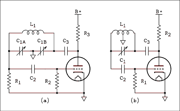
Parallel fed Colpits oscillator circuit
The circuit operates in a parallel-fed configuration, as the DC plate current does not pass through the inductor. R3 can be substituted with an RF choke if desired. Capacitor C3 prevents B+ from appearing across the variable capacitor, which is...
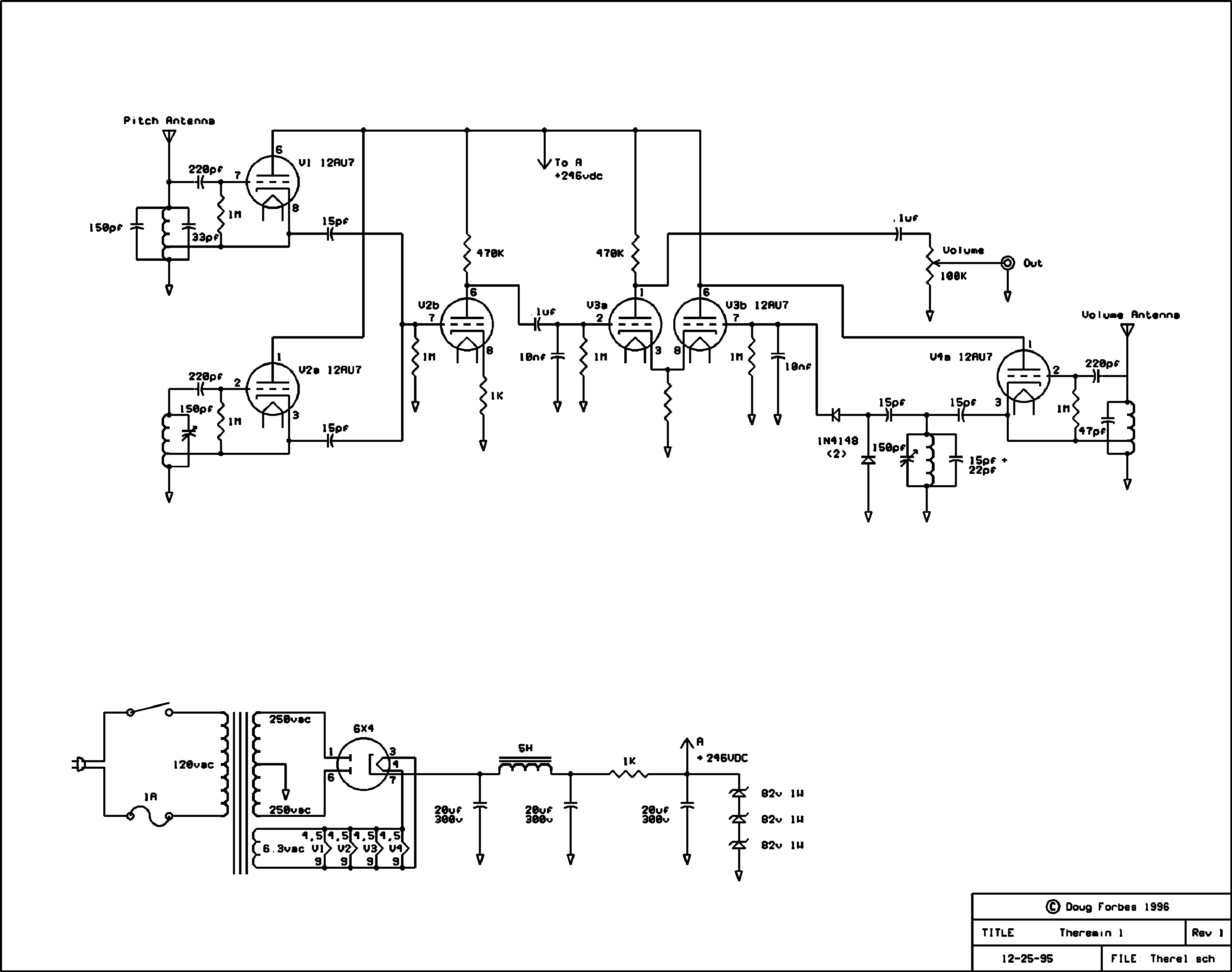
theremin
This was a quick experimental prototype based on a simple design by Doug Forbes, which utilizes common vacuum tubes. In its simplest form, a theremin operates by mixing two high-frequency oscillators—one fixed and the other tuned by the capacitance of...

LC feedback Oscillator
These are resonant circuits or tank circuit oscillators. They are commonly used to produce high frequencies ranging from 1 MHz to 500 MHz; hence, they are also known as RF oscillators. These oscillators are utilized in RF generators, radio transmitters,...

stable low frequency crystal
This is a design circuit for a Colpitts crystal oscillator. It is suitable for low-frequency crystal oscillator applications. Utilizing the 2N3823 JFET, this circuit exhibits excellent stability as temperature variations do not affect the loading of the 2N3823 JFET circuit.
The...
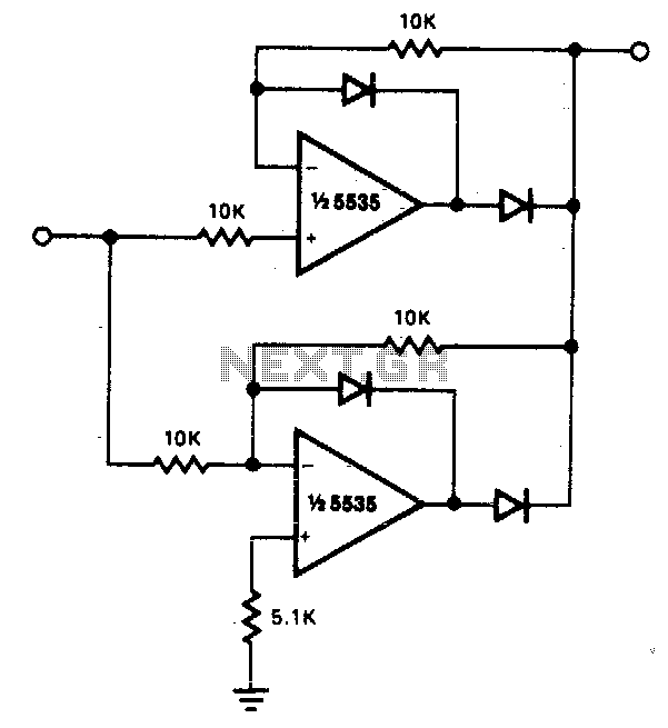
Precision full wave rectifier
The circuit facilitates precise full-wave rectification. It exhibits low output impedance for both input polarities, and the error rates remain minimal across all signal levels. It is important to note that the output will not be capable of sinking significant...

Pocket Theremin on the Cheap
Even if one is not familiar with the Theremin itself, it is likely that they have heard its distinctive electronic tones before. Remember those eerie soundtracks from 1950s science fiction movies? Chances are those oscillating noises were generated by a...
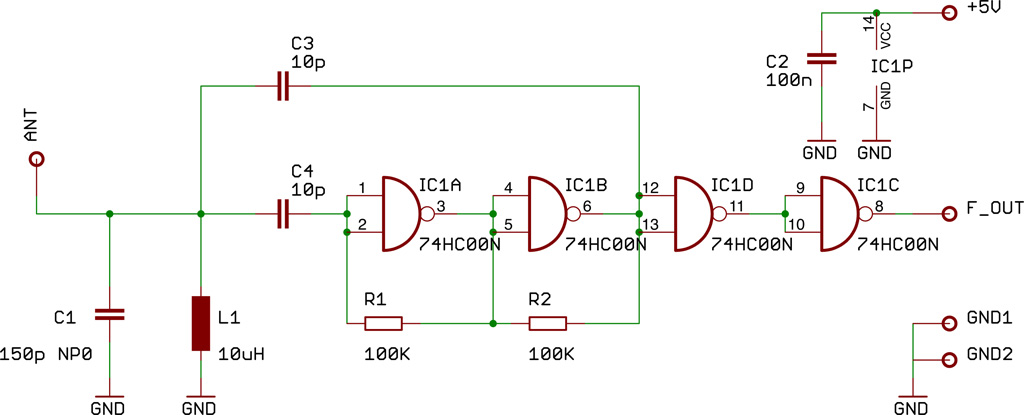
theremin as a capacitive sensing device
This document presents a compact Theremin module designed to connect to an Arduino board, which outputs sound to a speaker or generates control signals such as MIDI or servo commands. The device serves not only as a musical instrument but...
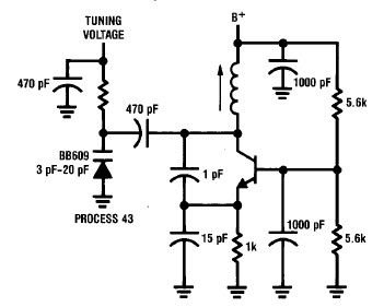
Simple 50 to 300 MHz Colpitts Oscillator
A simple high-efficiency Colpitts oscillator is utilized in higher frequency ranges, specifically above 50 MHz. Colpitts oscillators are preferred as stray circuit capacitance is in parallel with the desired feedback capacitance, preventing undesirable spurious resonances that may occur with the...
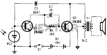
Electronic Music Maker
This electronic music maker utilizes an astable oscillator circuit that is regulated by a photocell. The intensity of light falling on the photocell influences the tone. By enclosing the circuit within a box, it is possible to manipulate the light-sensing...