


Sound level monitor
#sound level
#loudness detector
#555 IC
#Schmitt trigger
#audio monitoring
#voltage threshold
#sound measurement
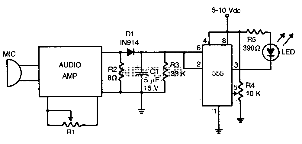
Description: A loudness detector is composed of a 555 integrated circuit (IC) configured as a Schmitt trigger. The output transitions from high to low when the input voltage exceeds a specified threshold. This threshold voltage is determined by the resistance value of R4.
The loudness detector circuit utilizes the 555 timer IC, which is a versatile and widely used component in various electronic applications. When configured as a Schmitt trigger, the 555 IC provides hysteresis in the output, which helps to eliminate noise from the input signal and ensures stable switching behavior.
In this configuration, the input voltage is continuously monitored. When the input voltage rises above the threshold set by the resistor R4, the output of the 555 IC switches from a high state (logic level '1') to a low state (logic level '0'). This transition can be used to trigger other circuits or devices, such as an LED indicator or a sound alert, indicating that a certain loudness level has been detected.
The threshold voltage is critical for the operation of the loudness detector. It is determined by the resistor R4, which is part of a voltage divider network. By adjusting the resistance of R4, the sensitivity of the detector can be modified, allowing it to respond to different levels of input voltage. This feature makes the circuit adaptable for various applications, such as audio processing, sound level monitoring, or automatic gain control systems.
In summary, the loudness detector circuit employing a 555 IC as a Schmitt trigger provides a reliable means of detecting loudness levels by utilizing a threshold voltage established by the resistor R4, thereby facilitating various audio-related applications.Loudness detector consists of a 555 IC wired as a Schmitt trigger. The output changes state—from high to low—whenever the input crosses a certain voltage That threshold voltage is established by the setting of R4.
The loudness detector circuit utilizes the 555 timer IC, which is a versatile and widely used component in various electronic applications. When configured as a Schmitt trigger, the 555 IC provides hysteresis in the output, which helps to eliminate noise from the input signal and ensures stable switching behavior.
In this configuration, the input voltage is continuously monitored. When the input voltage rises above the threshold set by the resistor R4, the output of the 555 IC switches from a high state (logic level '1') to a low state (logic level '0'). This transition can be used to trigger other circuits or devices, such as an LED indicator or a sound alert, indicating that a certain loudness level has been detected.
The threshold voltage is critical for the operation of the loudness detector. It is determined by the resistor R4, which is part of a voltage divider network. By adjusting the resistance of R4, the sensitivity of the detector can be modified, allowing it to respond to different levels of input voltage. This feature makes the circuit adaptable for various applications, such as audio processing, sound level monitoring, or automatic gain control systems.
In summary, the loudness detector circuit employing a 555 IC as a Schmitt trigger provides a reliable means of detecting loudness levels by utilizing a threshold voltage established by the resistor R4, thereby facilitating various audio-related applications.Loudness detector consists of a 555 IC wired as a Schmitt trigger. The output changes state—from high to low—whenever the input crosses a certain voltage That threshold voltage is established by the setting of R4.
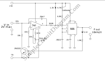
Voltage-To-Frequency Converter (VFC) with 555 IC
A voltage-to-frequency converter (VFC) circuit is depicted in the schematic diagram below. The circuit utilizes a 555 integrated circuit (IC) as the core component for its operation.
The voltage-to-frequency converter is a crucial component in various analog and digital applications,...
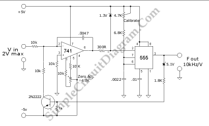
Voltage-To-Frequency Converter (VFC) with 555 IC
A voltage-to-frequency converter (VFC) circuit is illustrated in the schematic diagram below. The circuit utilizes a 555 integrated circuit (IC) as the central component of its operation.
The voltage-to-frequency converter (VFC) is a crucial electronic circuit that converts an input voltage...
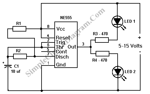
Led Flasher Circuit Using 555 IC
An LED flasher circuit can be constructed using a 555 integrated circuit (IC). The use of the 555 IC allows for greater flexibility in adjusting the flashing rate of the LED. This LED flasher circuit is similar to other designs.
The...
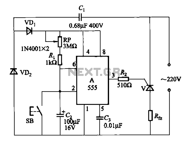
555 IC using a delay circuit of the four b
The 555 integrated circuit (IC) is utilized in a delay circuit configuration. It transitions from a high to a low output state when a button (SB) is pressed. The output remains high for a specified delay period before transitioning to...
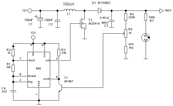
Boost ConverterCircuit Based On The 555 IC
The following circuit illustrates a Boost Converter Circuit Diagram. This circuit is based on the 555 IC. Features: it only requires off-the-shelf components.
The Boost Converter is a type of DC-DC converter that steps up the input voltage to a higher...
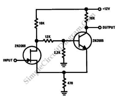
Discrete Schmitt Trigger
This is a Schmitt trigger circuit. This circuit produces a simple comparator action. It is emitter-coupled. This circuit has a distinct hysteresis loop.
The Schmitt trigger circuit is a fundamental electronic component utilized for signal conditioning, providing a means to convert...
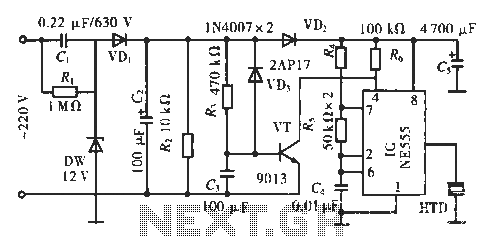
Parking call alarm circuit
The circuit utilizes a 555 integrated circuit (IC). When an incoming call is received, 220 V AC is stepped down through resistor R1, followed by rectification using diode VD1. A voltage regulator (DW) is employed, and capacitor C2 is used...
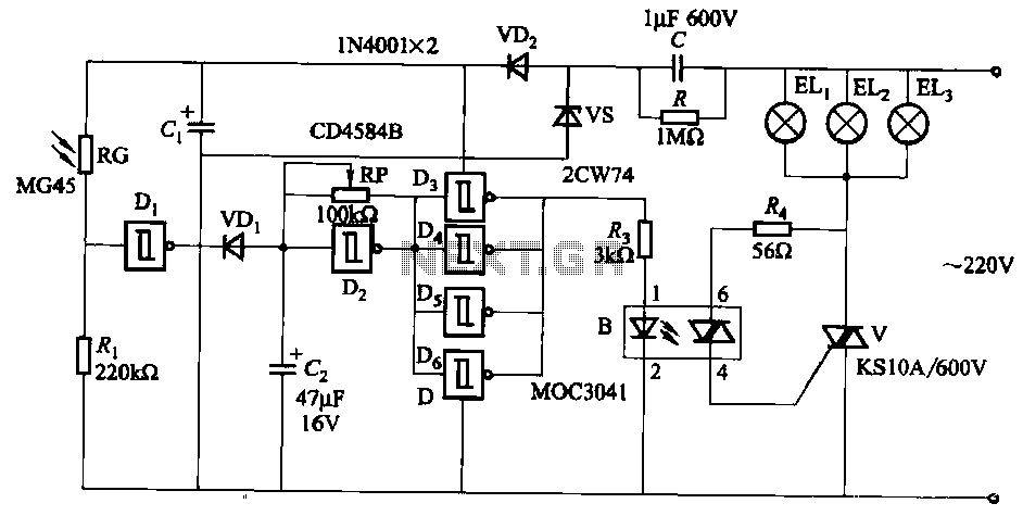
Three light control road construction warning light circuit
The circuit utilizes a CD4584B six Schmitt trigger integrated circuit (IC) with components Di and Ri forming a photometric circuit. D2, along with RP and C2, comprises an adjustable frequency ultra-low frequency oscillation device, where RP serves as an adjustment...
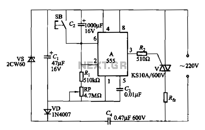
555 IC using a delay circuit ter
The circuit utilizes a 555 Integrated Circuit (IC) configured as a delay circuit. It transitions from a low to a high state after a button (SB) is pressed, initiating a delay before the output terminal goes high. The output remains...