


Speech Board for SPO256
#SPO256
#text-to-speech
#LM386
#PIC microcontroller
#amplifier
#speech synthesis
#audio circuit
#PIC12C508
#PIC12C509
#sound generation
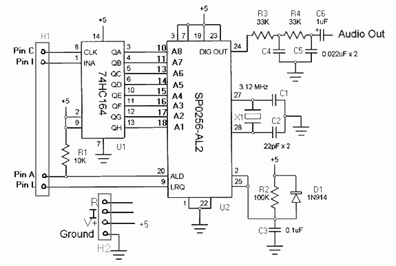
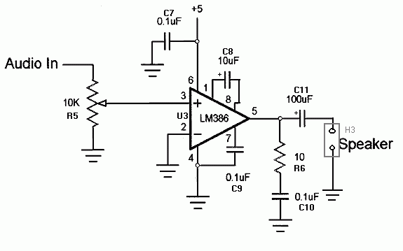
Description: This board does not utilize the CTS256AL2 text-to-speech chip. However, both SpeechChips.com and JDR may still have some of these chips available for purchase. The board can accommodate the SPO chip and an amplifier, allowing it to connect to a custom CTS circuit. Each necessary pin connection features a solder pad for off-board connections. Additionally, there is a socket for a 12C508/9 PIC, which can reduce the control pin count to two or even one. This setup enables the offloading of line-twiddling from the master controller, such as a Stamp. Most of the code has been developed, with some debugging and fine-tuning remaining. Both the PIC and audio amplifier (LM386) are optional, and there is provision for adding either an LED indicator or a separate power supply for the amplifier. The amplifier gain is 200, which is sufficient with a 5V supply. There is also space for a trimmer capacitor for the crystal if the SPO256 chip is particularly sensitive to clock stability. The board can accommodate a 5V voltage regulator if a regulated supply is not available, although this option is not recommended.
Design goals include a compact board size (hence the nested chips), minimal control lines (four), various construction options, and a high-quality circuit board. The layout was designed using ExpressPCB software. The board is double-sided, drilled, and solder reflowed, featuring four mounting holes at the corners, a solder mask, and silk-screening. The dimensions are approximately 1.5 inches by 2.5 inches (about 3.8 cm by 6.4 cm), with a densely packed design that places the shift register beneath the socket for the SPO-256. The bits are clocked out from the least significant bit (LSB) to the most significant bit (MSB). This board requires a moderate level of soldering proficiency and a fine soldering iron. It employs a shift register to convert serial input (not RS232 serial) to parallel for the SPO256, requiring only four control lines: C - CLK for the shift register (pin 0 in the circuit), I - INA for the shift register (pin 1), A - ALD allophone load for the SPO256 (pin 2), and L - LRQ for the SPO256 (pin 3).This board does NOT use the CTS256AL2 text-to-speech chip. [It would seem that both SpeechChips.com and JDR still have some of these chips, though, if you're looking for some.] However, you could easily use this board to hold the SPO chip and amplifier and connect it to your own CTS circuit. All necessary pin connections do have an available solder pad for off-board connections. Additionally, there is a socket for a 12C508/9 PIC which can reduce control pin count down to 2, or even to 1.
This would also allow the line-twiddling to be offloaded from the Stamp or whatever else is the master controller. I've done the bulk of the code with some debugging and fine-tuning left. Both the PIC and audio amp [LM386] are optional and there is a provision for adding either an LED on-indicator OR a separate power supply for the amp.
Amp gain is 200 and seems to be adequate with 5v supply. There is some room for a trimmer cap for the crystal in case your SPO256 chip is overly sensitive to the clock stability [as one of mine is]. The board can also be fitted with a 5v voltage regulator if you can't provide it with a regulated supply.
But this option is not recommended. Design goals: Small board size [hence the nested chips] Few control lines [4] Some construction options High quality circuit board Layed out with ExpressPCB s/w. [Visit Express PCB site (Manufacturing Specifications for Production Service) for more information about their product.] Double-sided, drilled, solder reflowed 4 mounting holes on corners solder mask silk screen.
Pretty small [1.5" x 2.5" (ca. 3.8 cm x 6.4 cm)] and fairly densely packed the shift register is UNDER the socket for the SPO-256 bits are clocked out from LSB to MSB This board equires a moderate level of soldering proficiency and a fine soldering iron. Uses shift register to convert serial input [NOT RS232 serial] to parallel for SPO256. Only requires 4 lines to control: C - CLK for shift register [pin 0 in circuit below] I - INA for shift register [pin 1] A - ALD allophone load for SPO256 [pin 2] L - LRQ for SPO256 [pin 3]
Design goals include a compact board size (hence the nested chips), minimal control lines (four), various construction options, and a high-quality circuit board. The layout was designed using ExpressPCB software. The board is double-sided, drilled, and solder reflowed, featuring four mounting holes at the corners, a solder mask, and silk-screening. The dimensions are approximately 1.5 inches by 2.5 inches (about 3.8 cm by 6.4 cm), with a densely packed design that places the shift register beneath the socket for the SPO-256. The bits are clocked out from the least significant bit (LSB) to the most significant bit (MSB). This board requires a moderate level of soldering proficiency and a fine soldering iron. It employs a shift register to convert serial input (not RS232 serial) to parallel for the SPO256, requiring only four control lines: C - CLK for the shift register (pin 0 in the circuit), I - INA for the shift register (pin 1), A - ALD allophone load for the SPO256 (pin 2), and L - LRQ for the SPO256 (pin 3).This board does NOT use the CTS256AL2 text-to-speech chip. [It would seem that both SpeechChips.com and JDR still have some of these chips, though, if you're looking for some.] However, you could easily use this board to hold the SPO chip and amplifier and connect it to your own CTS circuit. All necessary pin connections do have an available solder pad for off-board connections. Additionally, there is a socket for a 12C508/9 PIC which can reduce control pin count down to 2, or even to 1.
This would also allow the line-twiddling to be offloaded from the Stamp or whatever else is the master controller. I've done the bulk of the code with some debugging and fine-tuning left. Both the PIC and audio amp [LM386] are optional and there is a provision for adding either an LED on-indicator OR a separate power supply for the amp.
Amp gain is 200 and seems to be adequate with 5v supply. There is some room for a trimmer cap for the crystal in case your SPO256 chip is overly sensitive to the clock stability [as one of mine is]. The board can also be fitted with a 5v voltage regulator if you can't provide it with a regulated supply.
But this option is not recommended. Design goals: Small board size [hence the nested chips] Few control lines [4] Some construction options High quality circuit board Layed out with ExpressPCB s/w. [Visit Express PCB site (Manufacturing Specifications for Production Service) for more information about their product.] Double-sided, drilled, solder reflowed 4 mounting holes on corners solder mask silk screen.
Pretty small [1.5" x 2.5" (ca. 3.8 cm x 6.4 cm)] and fairly densely packed the shift register is UNDER the socket for the SPO-256 bits are clocked out from LSB to MSB This board equires a moderate level of soldering proficiency and a fine soldering iron. Uses shift register to convert serial input [NOT RS232 serial] to parallel for SPO256. Only requires 4 lines to control: C - CLK for shift register [pin 0 in circuit below] I - INA for shift register [pin 1] A - ALD allophone load for SPO256 [pin 2] L - LRQ for SPO256 [pin 3]
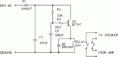
Amplifier Output Delay with Relay Schematic Diagram
This is a minimal circuit designed for individual audio amplifier projects to control the presenter output relay. The purpose of this circuit is to manage the relay that activates the speaker output within the audio amplifier. The circuit introduces a...
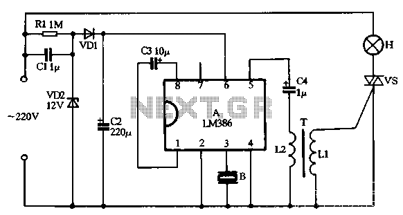
LM386 making music with a voice-activated lights circuit
VD1, VD2, C1, and C2 comprise a simple half-wave rectifier capacitor step-down voltage regulator circuit, providing an output of approximately 12V for a linear power supply connected to the LM386. The LM386 is linked to the inverting input terminal (pin...
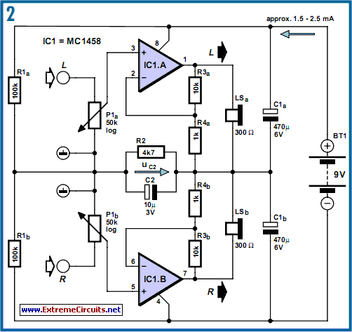
DC-Coupled Audio Amplifier circuit
Designs for audio amplifiers with DC coupling to the load are not frequently seen today, despite offering distinct advantages.
Audio amplifiers that employ DC coupling to the load provide several benefits that can enhance performance in specific applications. In traditional audio...
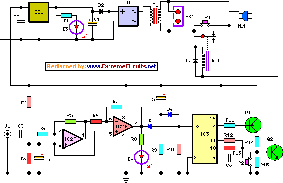
amplifier timer circuit schematic
This circuit deactivates an amplifier or any connected device when a low-level audio signal at its input is absent for at least 15 minutes. By pressing P1, the device is powered on, supplying power to any appliance connected to SK1....
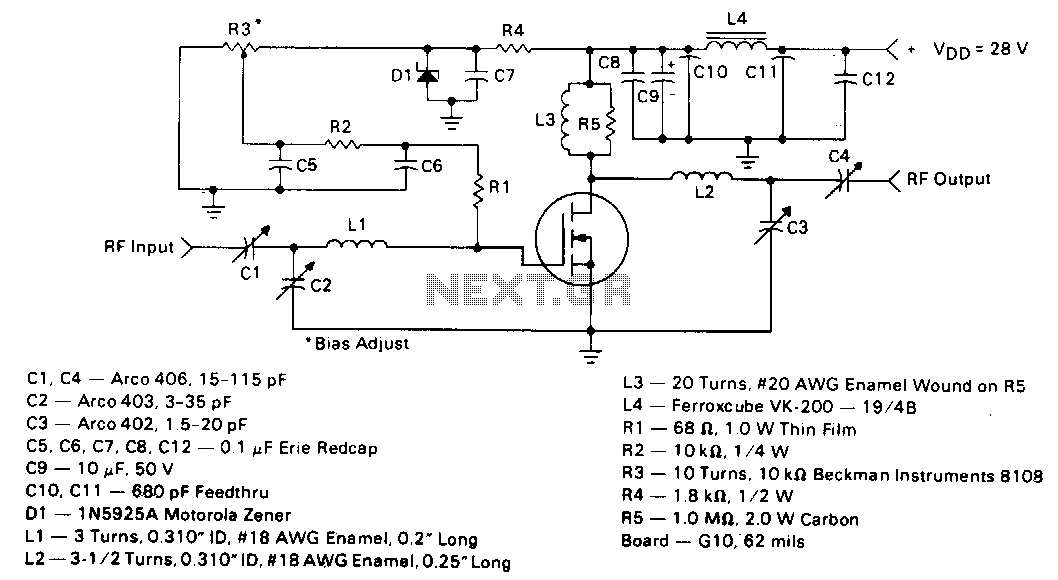
5W-150mhz-amplifier
This circuit employs the MRF123 TMOS power FET. The MRF134 is a high-gain FET that may exhibit instability at both VHF and UHF frequencies. A 68-ohm input loading resistor has been used to improve stability. This amplifier achieves a gain...
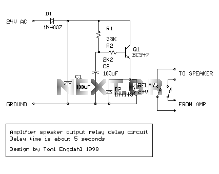
amplifier delay output relay
This is a simple circuit which I built to one of my audio amplifier projects to control the speaker output relay. The purpose of this circuit is to control the relay which turns on the speaker output relay in the...
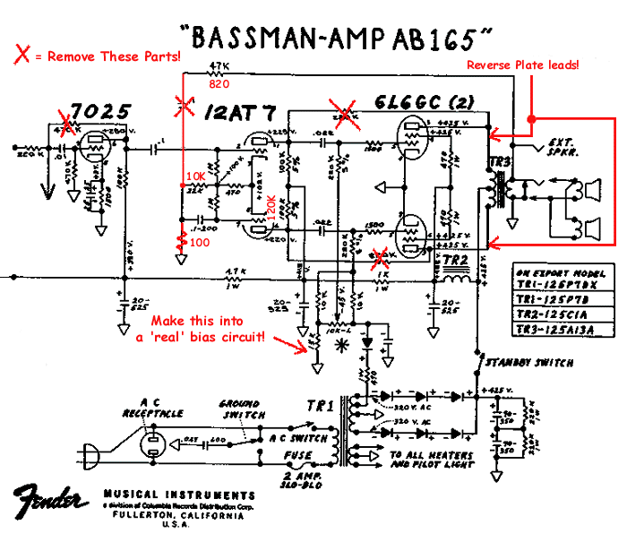
Bassman Modifications
Upgrading to a 3-prong AC cord is a common modification, as is the replacement of filter capacitors. Switching coupling capacitors to brands like Orange Drops or other boutique options is also popular, often enhancing the appeal in online auctions. Additional...
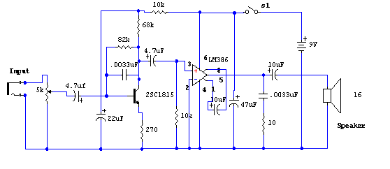
Signal Tracer
The primary component of this circuit is the LM386 amplifier chip. Additionally, it incorporates a transistor input to buffer the input signal and provide additional gain for the LM386.
The LM386 is a low-voltage audio power amplifier capable of delivering up...
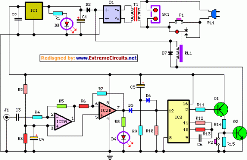
Amplifier Timer Circuit Schematic
This circuit turns off an amplifier or any other device when a low-level audio signal fed to its input is absent for at least 15 minutes. Pressing P1 switches the device on, supplying power to any appliance connected to SK1....