


Tone selector circuit
#tone selector
#equalizer
#amplifier
#IC
#RC components
#electromagnetic
#phono
#audio circuit
#signal processing
#sound control
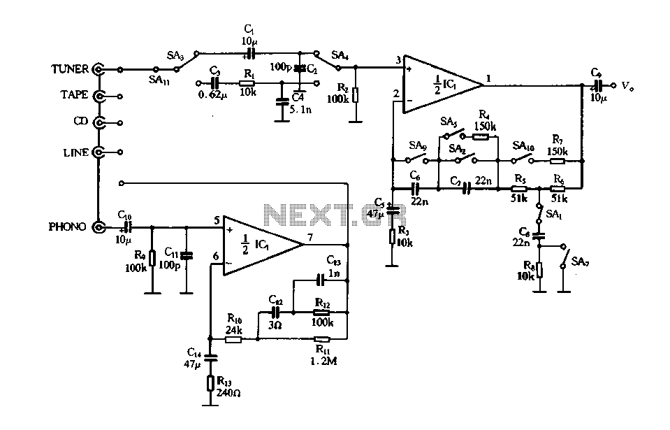
Description: Figure 4-12 illustrates a five-speed tone selector schematic, which includes circuit components such as IC1, an electromagnetic phono equalizer amplifier, and external RC components. The schematic also features a selection switch for the tone control circuit. When the straight button (SA1, SA2) is pressed, it activates the negative feedback loop within the T-type network (C8, Rs), disconnecting Rs and short-circuiting C7, resulting in a typical linear amplifier gain determined by the sum of resistors R5 and R6, which maintains a flat output characteristic. When the language key (SA1, SPk) is pressed, it positions SA1 and SA2 similarly to the straight key, ensuring the amplifier's frequency response remains flat. The amplifier input is terminated with SA3 and SA4, which form a bandpass filter that allows signals in the 200 to 3000 Hz range to pass with a 6dB/octave audio attenuation. Pressing the play button activates a parallel resistor (R4) with C7, slightly improving the high-bass response. The orchestral key (SA7) short-circuits the T-type network, grounding C8 to enhance bass. When the bass key (SA9, SA10) is activated, it engages a negative feedback loop through capacitor B, improving bass while slightly enhancing treble. The T-type network and resistor R7 work together to balance treble and bass, utilizing a 5-position interlocking key switch.
The schematic represents a sophisticated tone control system designed for audio applications, allowing users to tailor the sound output to their preferences. The five-speed tone selector provides versatility in sound adjustment, enabling fine-tuning of audio characteristics. The use of a T-type network in conjunction with various feedback loops and passive components ensures that the amplifier maintains a desired frequency response while allowing for enhancements in specific audio ranges.
The circuit's design incorporates a combination of resistors and capacitors to create a stable and adjustable equalization effect. The negative feedback loops are crucial in maintaining linearity and preventing distortion, which is vital for high-fidelity audio reproduction. The inclusion of a bandpass filter further refines the audio output, ensuring that only the desired frequency ranges are amplified, thus enhancing the overall listening experience.
In operation, the user can easily switch between different tone settings using the interlocking key switch, which mechanically prevents multiple selections from being activated simultaneously. This feature ensures reliable operation and prevents potential signal interference that could arise from simultaneous engagement of different tone control settings. Overall, the design reflects a careful consideration of audio engineering principles, emphasizing clarity, control, and user flexibility in sound modulation.Figure 4-12 is a five-speed type tone selector schematics o as follows: circuit, IC1 and other components electromagnetic phono equalizer amplifier, I bar and external RC compo nents and composition of the selection switch tone tune selector circuit. Press the straight button, sAl, SA2 action, SAi negative feedback loop in the T-type network c8.. Rs disconnect, saz will C7 short-circuit to be a typical linear amplifier gain is determined by the advocate 3 (R5 + R6), having a flat output characteristic straight. Press the Language key, SAi ~ SPk action, SAl, SA2 position with the straight key, the amplifier frequency response was flat state.
SA3, SA4 at the amplifier input termination people bandpass filter passband is. :, 200 ~ 3000Hz band signal by a 6dB/f audio attenuation. When you press the play button, carved altar of the parallel operation of a resistor R4 on the C7, the high-bass slightly improved. When you press the orchestral key, SA7 action, T-type network people are short-circuited, C8 ground bass are to be mentioned liters.
Press the bass is key, S: Ag, SAio action, catch the negative feedback loop capacitor b, C series, treble negative feedback enhanced bass can be improved, SAio with the network of T-type people and the resistance R7, so treble slightly, the discharge pitch bass balance electricity use 5 4 interlocking key switch.
The schematic represents a sophisticated tone control system designed for audio applications, allowing users to tailor the sound output to their preferences. The five-speed tone selector provides versatility in sound adjustment, enabling fine-tuning of audio characteristics. The use of a T-type network in conjunction with various feedback loops and passive components ensures that the amplifier maintains a desired frequency response while allowing for enhancements in specific audio ranges.
The circuit's design incorporates a combination of resistors and capacitors to create a stable and adjustable equalization effect. The negative feedback loops are crucial in maintaining linearity and preventing distortion, which is vital for high-fidelity audio reproduction. The inclusion of a bandpass filter further refines the audio output, ensuring that only the desired frequency ranges are amplified, thus enhancing the overall listening experience.
In operation, the user can easily switch between different tone settings using the interlocking key switch, which mechanically prevents multiple selections from being activated simultaneously. This feature ensures reliable operation and prevents potential signal interference that could arise from simultaneous engagement of different tone control settings. Overall, the design reflects a careful consideration of audio engineering principles, emphasizing clarity, control, and user flexibility in sound modulation.Figure 4-12 is a five-speed type tone selector schematics o as follows: circuit, IC1 and other components electromagnetic phono equalizer amplifier, I bar and external RC compo nents and composition of the selection switch tone tune selector circuit. Press the straight button, sAl, SA2 action, SAi negative feedback loop in the T-type network c8.. Rs disconnect, saz will C7 short-circuit to be a typical linear amplifier gain is determined by the advocate 3 (R5 + R6), having a flat output characteristic straight. Press the Language key, SAi ~ SPk action, SAl, SA2 position with the straight key, the amplifier frequency response was flat state.
SA3, SA4 at the amplifier input termination people bandpass filter passband is. :, 200 ~ 3000Hz band signal by a 6dB/f audio attenuation. When you press the play button, carved altar of the parallel operation of a resistor R4 on the C7, the high-bass slightly improved. When you press the orchestral key, SA7 action, T-type network people are short-circuited, C8 ground bass are to be mentioned liters.
Press the bass is key, S: Ag, SAio action, catch the negative feedback loop capacitor b, C series, treble negative feedback enhanced bass can be improved, SAio with the network of T-type people and the resistance R7, so treble slightly, the discharge pitch bass balance electricity use 5 4 interlocking key switch.
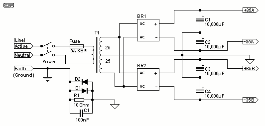
Power Supply For Amplifiers
For the 60W amplifier, a nominal (full load) supply of +/- 35V is required, so a 25-0-25 secondary is ideal - however, see Updates, below. The circuit for the supply is shown below, and uses separate rectifiers, capacitors and fuses...
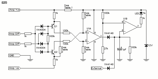
Amplifier Clipping Indicator
At some stage, we will all find ourselves pushing hi-fi equipment just a little too hard, and if lucky, will just find that the sound has become "dirty". If this happens too often or is too severe, tweeters are the...
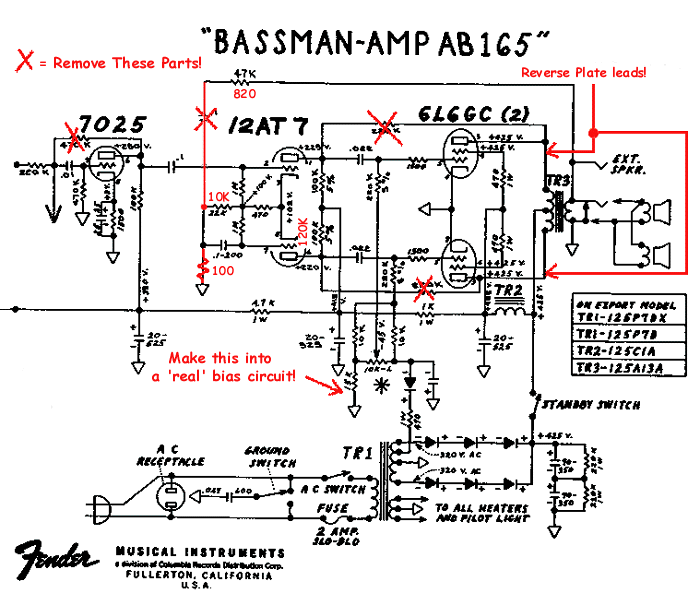
Bassman Modifications
Upgrading to a 3-prong AC cord is a common modification, as is the replacement of filter capacitors. Switching coupling capacitors to brands like Orange Drops or other boutique options is also popular, often enhancing the appeal in online auctions. Additional...
gated pulse descrambler
This circuit consists of an amplifier and a video detector with a second subcarrier detector for synchronization recovery purposes. A pulse-former circuit modulates the gain of the main channel, increasing it during synchronization intervals.
The circuit is designed to enhance video...
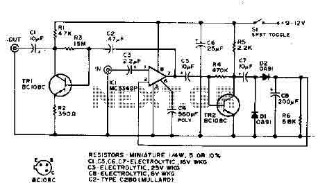
Amplifier Compressor MC3340P
The output is rectified, and TR2 controls the gain of the ICL. This audio compressor circuit uses an MC3340P as a variable gain amplifier.
The audio compressor circuit described utilizes an MC3340P integrated circuit, which functions as a variable gain amplifier...
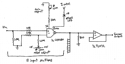
Interpolating Scanner Circuit
This design is for an interpolating scanner, a circuit featuring multiple signal inputs, a control voltage input, and a signal output. The output selectively transitions between inputs, smoothly fading from one to the next as the control voltage increases. A...
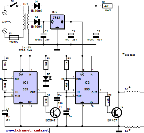
pipe descaler schematics
For many years, magnetic (or electromagnetic) water descaler devices have appeared on the shelves of home improvement and DIY stores across Europe. Despite numerous studies conducted by manufacturers and various consumer associations, none have definitively concluded on the effectiveness of...
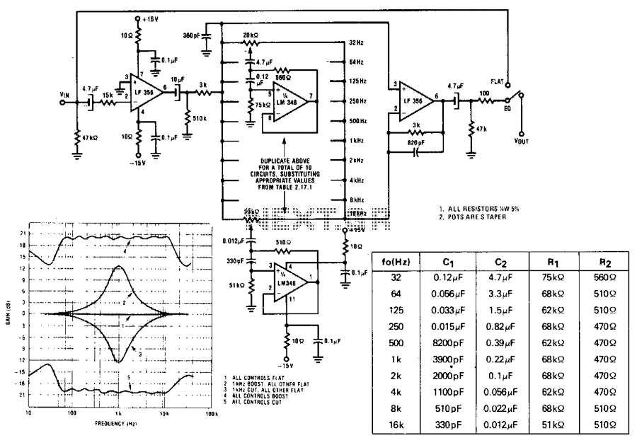
Ten-band-octave-equalizer
A series of active RF filters using the National LM3481C comprises a ten-band graphic equalizer. C1, C2, R1, and R2 should be at least 10% with 5% preferred tolerances.
The circuit design features a ten-band graphic equalizer that utilizes a series...
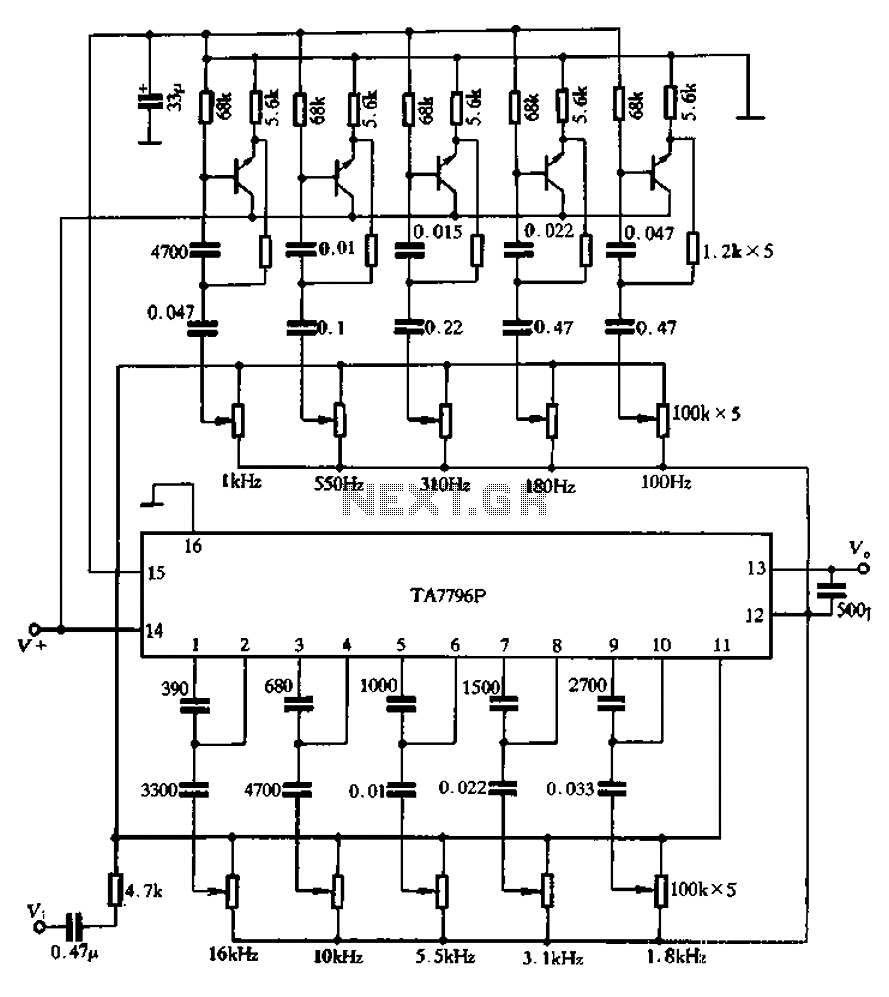
Using an external transistor ten-band equalizer
Another application example is presented. It utilizes the TA7796 IC along with five external transistors to create a ten-band equalizer circuit. The lowest center frequency of the equalizer is set at 100 Hz, while the highest center frequency of the...