


Updated Circuit Details for Clara Rockmores Theremin
#theremin
#audio circuit
#Bob Moog
#instrument
#schematic
#recreation
#Adrian Bontenbal
#Clara Rockmore
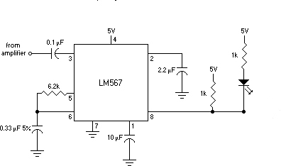
Description: Adrian Bontenbal has provided updated notes from his experiments in recreating Clara Rockmore's theremin. Bob Moog shared his hand-drawn schematic for Clara's instrument over a decade ago. Adrian started with that schematic to build his own Rockmore theremin. During the process, he encountered some challenges and adjusted certain component values. He has now returned with further updates, including a timbre selection circuit and a new tone decoder circuit that indicates when the player is producing a perfect 440Hz tone. This feature appears to be quite beneficial and is something that could enhance the functionality of many theremins.
The recreated Rockmore theremin, based on Bob Moog's original schematic, serves as a testament to the enduring legacy of early electronic instruments. The design incorporates several key components that contribute to its unique sound and functionality. The timbre selection circuit allows the player to modify the tonal characteristics of the theremin, enabling a range of sound textures suitable for various musical styles. This circuit typically consists of a series of capacitors and resistors that can be switched in and out of the signal path, effectively altering the frequency response of the instrument.
The newly added tone decoder circuit is a significant enhancement, providing real-time feedback to the performer. This circuit utilizes a frequency detection algorithm to identify when the theremin is producing a tone at precisely 440Hz, which corresponds to the musical note A above middle C. This feature not only aids in tuning but also assists players in achieving desired pitch accuracy during performances. The implementation of this circuit may involve the use of a microcontroller or dedicated frequency detection IC, which processes the output signal from the theremin's oscillators.
Overall, the combination of these updated features—timbre selection and tone detection—offers a modern touch to the classic design of the theremin, making it more accessible and versatile for contemporary musicians. The adjustments made to component values further enhance the instrument's performance, ensuring that it meets the expectations of both novice and experienced players. This evolution of Clara Rockmore's theremin exemplifies the continuous innovation within the field of electronic music instruments.Adrian Bontenbal has provided us with updated notes from his experiments in building a re-creation of Clara Rockmore`s theremin. As you`ll recall, Bob Moog shared his hand-drawn schematic for Clara`s instrument over a decade ago. Adrian started with that schematic and built his own Rockmore theremin! Along the way, he ran into some snags and debugg ed some component values. Now, he`s back with more updates including a timbre selection circuit and a new tone decoder circuit that shows the player when they`re striking a perfect 440Hz tone. This sounds like a very useful feature to me - something I wish more theremins had built-in.
The recreated Rockmore theremin, based on Bob Moog's original schematic, serves as a testament to the enduring legacy of early electronic instruments. The design incorporates several key components that contribute to its unique sound and functionality. The timbre selection circuit allows the player to modify the tonal characteristics of the theremin, enabling a range of sound textures suitable for various musical styles. This circuit typically consists of a series of capacitors and resistors that can be switched in and out of the signal path, effectively altering the frequency response of the instrument.
The newly added tone decoder circuit is a significant enhancement, providing real-time feedback to the performer. This circuit utilizes a frequency detection algorithm to identify when the theremin is producing a tone at precisely 440Hz, which corresponds to the musical note A above middle C. This feature not only aids in tuning but also assists players in achieving desired pitch accuracy during performances. The implementation of this circuit may involve the use of a microcontroller or dedicated frequency detection IC, which processes the output signal from the theremin's oscillators.
Overall, the combination of these updated features—timbre selection and tone detection—offers a modern touch to the classic design of the theremin, making it more accessible and versatile for contemporary musicians. The adjustments made to component values further enhance the instrument's performance, ensuring that it meets the expectations of both novice and experienced players. This evolution of Clara Rockmore's theremin exemplifies the continuous innovation within the field of electronic music instruments.Adrian Bontenbal has provided us with updated notes from his experiments in building a re-creation of Clara Rockmore`s theremin. As you`ll recall, Bob Moog shared his hand-drawn schematic for Clara`s instrument over a decade ago. Adrian started with that schematic and built his own Rockmore theremin! Along the way, he ran into some snags and debugg ed some component values. Now, he`s back with more updates including a timbre selection circuit and a new tone decoder circuit that shows the player when they`re striking a perfect 440Hz tone. This sounds like a very useful feature to me - something I wish more theremins had built-in.
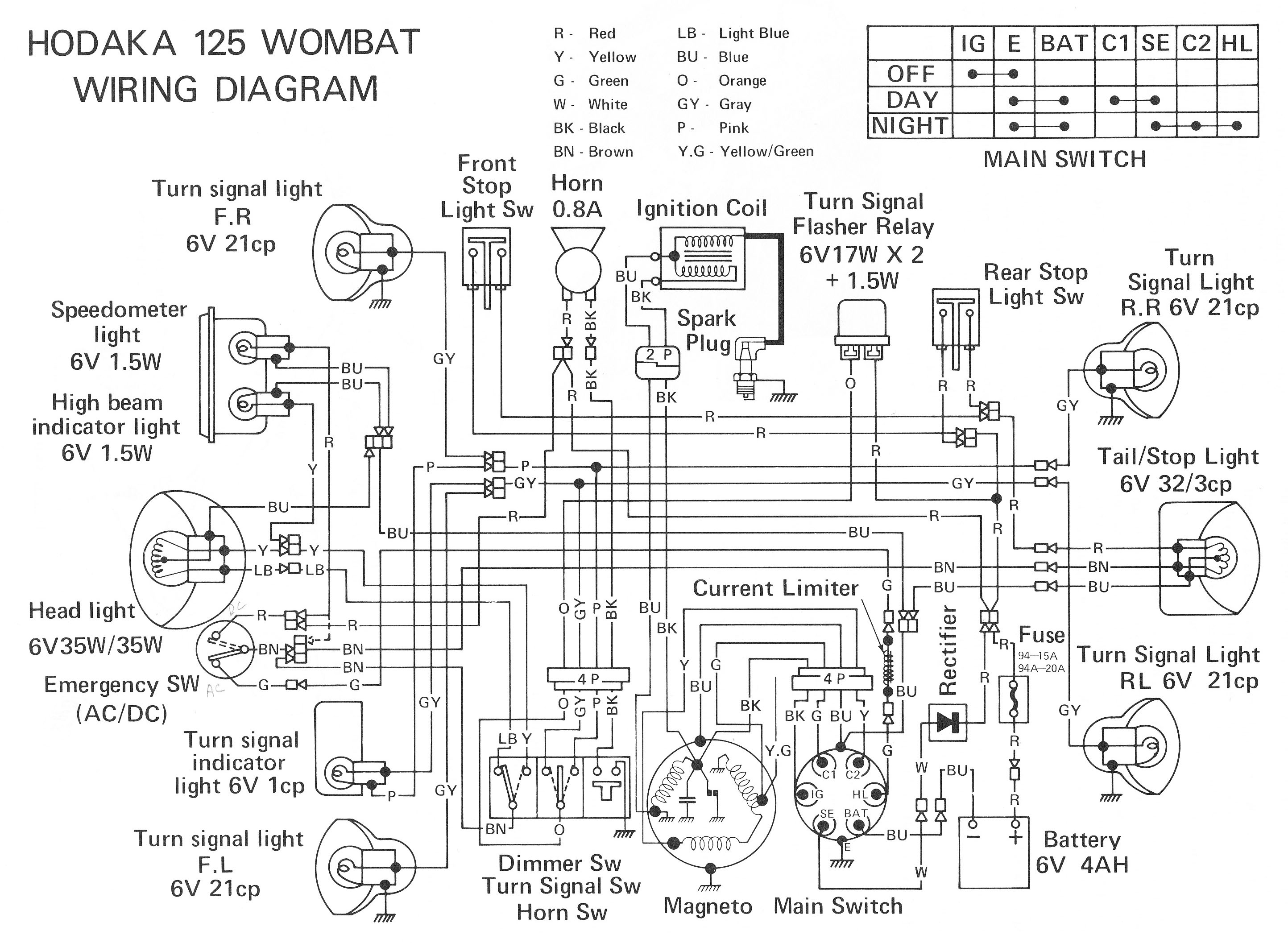
ELECTRONIC SCHEMATIC CIRCUIT DIAGRAMS
Electronic Schematic Circuit Diagrams Manual PDF Download.
The document provides a comprehensive manual that focuses on electronic schematic circuit diagrams. These diagrams are essential tools for understanding and designing electronic circuits, offering visual representations of circuit components and their interconnections. The...
metal detector project circuit
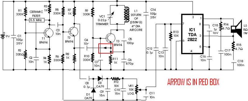
A schematic diagram for a metal detector has been found. The project does not need to be original and can be sourced from the internet. There are several questions regarding this schematic. One query pertains to a small arrow connected...
Optical Theremin
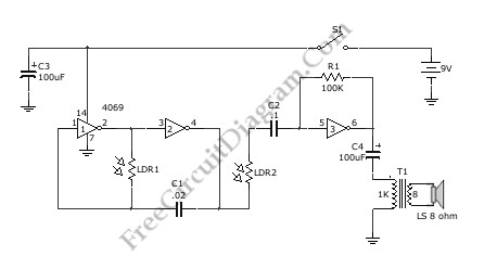
A Theremin circuit is illustrated in the schematic diagram below, utilizing various methods to control pitch. The oscillator of this tone generator allows both volume and frequency to be adjusted using LDRs (Light Dependent Resistors), which are light-sensitive electronic components....
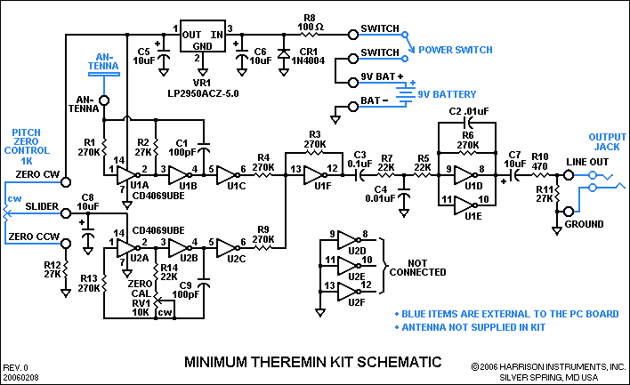
Minimum Theremin Schematic
Two identical integrated circuits, U1 and U2, known as "hex inverters," are utilized for the primary functions of the theremin. These are CMOS (Complementary Symmetry Metal Oxide Semiconductor) devices commonly employed in digital circuits to perform a logic function referred...
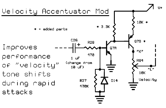
Fred Nachbaurs Theremax modifications
The purpose of this page is not to provide a comprehensive review of this popular theremin design, nor to introduce the intriguing world of theremins in general. For those unfamiliar with theremins, links are available on the index page. However,...
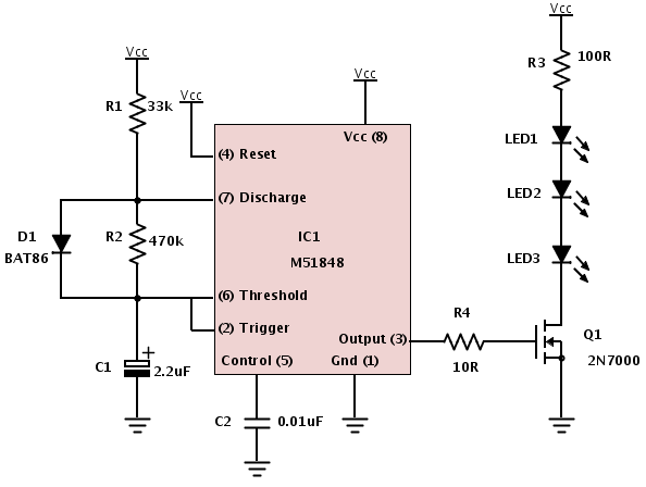
Building a device from a schematic
A common issue encountered is that individuals possess a schematic, also known as a circuit diagram, that they wish to construct. However, they discover that there are...
Building a circuit from a schematic requires a clear understanding of the components involved...
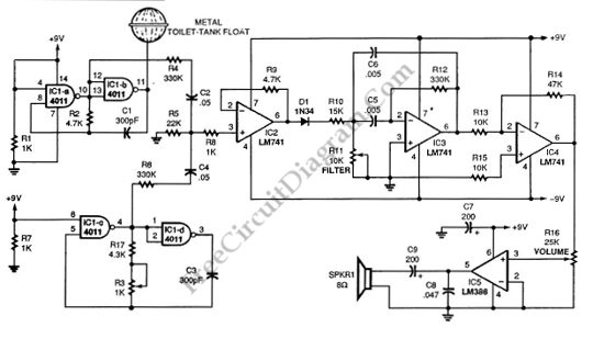
Single Chip Theremin Circuit
This schematic diagram illustrates a single-chip Theremin circuit. A Theremin is an electronic musical instrument that detects hand movements to control tones and frequency. The circuit employs two separate Colpitts LC oscillators to generate a beat frequency. The frequencies of...
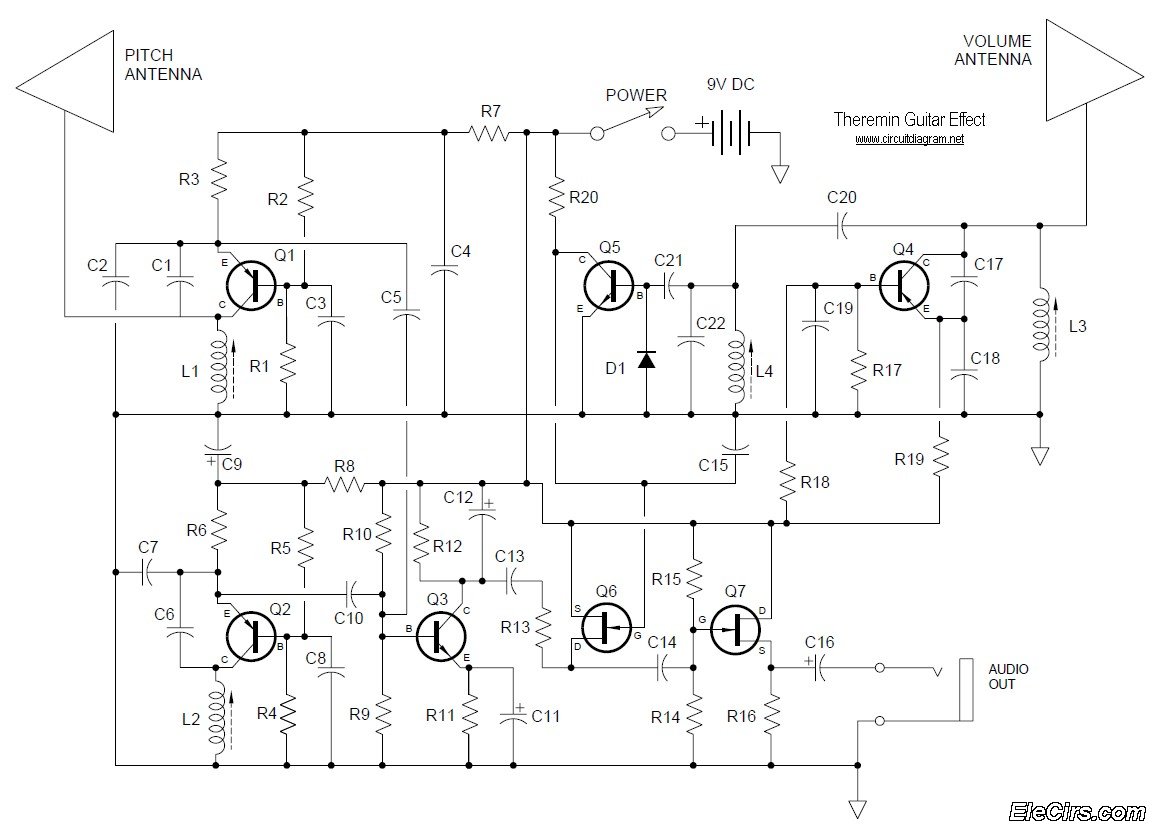
Theremin Music Instrument circuit diagram
Below is the circuit diagram for the Theremin music instrument effect. A guitar or instrument amplifier is an ideal companion for the Theremin, allowing for bass or treble boost as desired, as well as fuzz (distortion) or reverberation if these...
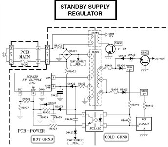
Need to have the circuit schematic for LG 29SA1RL model
The schematic is in PDF format and cannot be sent through this site. It is recommended to check a specific website that contains various schematics, including older posts that might have the schematic needed. A WS-55807 model is experiencing issues...