


Wah pedal for Guitar
#guitar
#wah pedal
#potentiometer
#frequency control
#mini-toggle switch
#audio effect
#resonance control
#pc board
#wiring

Description: The right way to do this is with a small extra pc board to accommodate the new components, firmly secured inside the case, and wired carefully and neatly. Unfortunately, I did none of these things, but it worked reliably and if it ain't broke. I used a pot for the resonance control mounted just forward of the socket on the side of the case, and I used a three position ON-ON-ON mini-toggle (these can be wired as a single pole, 3 way switch) for three frequency ranges. This switch is small and fits behind the socket. You could use a rotary switch, but you need to be sure it fits in the case, of course.
More: I wired the 1M resistor direct on the circuit board, and carefully removed the .01uF capacitor and 33K resistor, wiring a 10K resistor soldered at one end only. This is really quite shabby, but given that its all enclosed, has been reliable.
Equally shabby, the 1M resistors are located on the back of the switch, with the 3 capacitors wired at one end on the switch and all wired together at the other end. Using caps with solid wires this is really quite strong, but doesn't look good, and would not pass any serious quality inspection.
Nevertheless, its a foot pedal, and gets kicked around, and it still works. I should admit that despite this new flexibility, 95% of the time I use the standard settings.
Replace the 33K resistor across the coil with a 10K resistor in series with a 50K Linear pot. When this pot is centred, the standard value is restored. Switch different value capacitors for the standard 0.01 value at one end of the coil. Increasing this value 4 times decreases the frequency range by a factor of 2. There are some suggested values on the circuit for a 5-way switch, where the centre position is standard. The 1M resistors prevent a loud popping sound when you turn the switch. Replace the SPDT footswitch with a DPDT switch and wire it as above for a true bypass switch. Note the addition of a 1M resistor on the input switch.
A compact circuit board design is suggested for integrating additional components into the existing foot pedal. The board should be securely mounted within the casing to ensure stability during operation. The resonance control is implemented using a potentiometer, which should be positioned conveniently for user access. A three-position ON-ON-ON mini-toggle switch is employed to select among three frequency ranges, providing versatility in sound modulation. This switch, being compact, is designed to fit behind the socket, but careful consideration of dimensions is necessary if opting for a rotary switch instead.
The circuit modification includes direct soldering of a 1M resistor on the circuit board, while altering the configuration of capacitors and resistors. The original .01uF capacitor and 33K resistor are replaced with a single 10K resistor, enhancing the circuit's functionality, albeit with a less refined appearance. The arrangement of resistors and capacitors on the switch must ensure strong connections, particularly those utilizing solid wire components, while acknowledging that aesthetic quality may be compromised.
The design supports a standard operation mode, with the option to adjust settings as needed. A 10K resistor is placed in series with a 50K linear potentiometer to facilitate variable resistance, allowing users to revert to standard values when the potentiometer is centered. The frequency range can be modified by switching capacitors, with the potential to halve the frequency range by increasing the capacitance value.
To enhance the pedal's functionality, replacing the single-pole double-throw (SPDT) footswitch with a double-pole double-throw (DPDT) switch is recommended. This modification enables true bypass functionality, ensuring that the signal path remains unaltered when the effect is disengaged. An additional 1M resistor should be incorporated into the input switch configuration to mitigate any unwanted noise during operation.The right way to do this is with a small extra pc board to accommodate the new components, firmly secured inside the case, and wired carefully and neatly. Unfortunately, I did none of these things, but it worked reliably and if it ain't broke. I used a pot for the resonance control mounted just forward of the socket on the side of the case, and I used a three position ON-ON-ON mini-toggle (these can be wired as a single pole, 3 way switch) for three frequency ranges.
This switch is small and fits behind the socket. You could use a rotary switch, but you need to be sure it fits in the case, of course. I wired the 1M resistor direct on the circuit board, and *carefully* removed the .01uF capacitor and 33K resistor, wiring a 10K resistor soldered at one end only. This is really quite shabby, but given that its all enclosed, has been reliable. Equally shabby, the 1M resistors are located on the back of the switch, with the 3 capacitors wired at one end on the switch and all wired together at the other end.
Using caps with solid wires this is really quite strong, but doesn't look good, and would not pass any serious quality inspection. Nevertheless, its a foot pedal, and gets kicked around, and it still works. I should admit that despite this new flexibility, 95% of the time I use the standard settings. Replace the 33K resistor across the coil with a 10K resistor in series with a 50K Linear pot. When this pot is centred, the standard value is restored. Switch different value capacitors for the standard 0.01 value at one end of the coil. Increasing this value 4 times decreases the frequency range by a factor of 2. There are some suggested values on the circuit for a 5-way switch, where the centre position is standard.
The 1M resistors prevent a loud popping sound when you turn the switch. Replace the SPDT footswitch with a DPDT switch and wire it as above for a true bypass switch. Note the addition of a 1M resistor on the input switch.
More: I wired the 1M resistor direct on the circuit board, and carefully removed the .01uF capacitor and 33K resistor, wiring a 10K resistor soldered at one end only. This is really quite shabby, but given that its all enclosed, has been reliable.
Equally shabby, the 1M resistors are located on the back of the switch, with the 3 capacitors wired at one end on the switch and all wired together at the other end. Using caps with solid wires this is really quite strong, but doesn't look good, and would not pass any serious quality inspection.
Nevertheless, its a foot pedal, and gets kicked around, and it still works. I should admit that despite this new flexibility, 95% of the time I use the standard settings.
Replace the 33K resistor across the coil with a 10K resistor in series with a 50K Linear pot. When this pot is centred, the standard value is restored. Switch different value capacitors for the standard 0.01 value at one end of the coil. Increasing this value 4 times decreases the frequency range by a factor of 2. There are some suggested values on the circuit for a 5-way switch, where the centre position is standard. The 1M resistors prevent a loud popping sound when you turn the switch. Replace the SPDT footswitch with a DPDT switch and wire it as above for a true bypass switch. Note the addition of a 1M resistor on the input switch.
A compact circuit board design is suggested for integrating additional components into the existing foot pedal. The board should be securely mounted within the casing to ensure stability during operation. The resonance control is implemented using a potentiometer, which should be positioned conveniently for user access. A three-position ON-ON-ON mini-toggle switch is employed to select among three frequency ranges, providing versatility in sound modulation. This switch, being compact, is designed to fit behind the socket, but careful consideration of dimensions is necessary if opting for a rotary switch instead.
The circuit modification includes direct soldering of a 1M resistor on the circuit board, while altering the configuration of capacitors and resistors. The original .01uF capacitor and 33K resistor are replaced with a single 10K resistor, enhancing the circuit's functionality, albeit with a less refined appearance. The arrangement of resistors and capacitors on the switch must ensure strong connections, particularly those utilizing solid wire components, while acknowledging that aesthetic quality may be compromised.
The design supports a standard operation mode, with the option to adjust settings as needed. A 10K resistor is placed in series with a 50K linear potentiometer to facilitate variable resistance, allowing users to revert to standard values when the potentiometer is centered. The frequency range can be modified by switching capacitors, with the potential to halve the frequency range by increasing the capacitance value.
To enhance the pedal's functionality, replacing the single-pole double-throw (SPDT) footswitch with a double-pole double-throw (DPDT) switch is recommended. This modification enables true bypass functionality, ensuring that the signal path remains unaltered when the effect is disengaged. An additional 1M resistor should be incorporated into the input switch configuration to mitigate any unwanted noise during operation.The right way to do this is with a small extra pc board to accommodate the new components, firmly secured inside the case, and wired carefully and neatly. Unfortunately, I did none of these things, but it worked reliably and if it ain't broke. I used a pot for the resonance control mounted just forward of the socket on the side of the case, and I used a three position ON-ON-ON mini-toggle (these can be wired as a single pole, 3 way switch) for three frequency ranges.
This switch is small and fits behind the socket. You could use a rotary switch, but you need to be sure it fits in the case, of course. I wired the 1M resistor direct on the circuit board, and *carefully* removed the .01uF capacitor and 33K resistor, wiring a 10K resistor soldered at one end only. This is really quite shabby, but given that its all enclosed, has been reliable. Equally shabby, the 1M resistors are located on the back of the switch, with the 3 capacitors wired at one end on the switch and all wired together at the other end.
Using caps with solid wires this is really quite strong, but doesn't look good, and would not pass any serious quality inspection. Nevertheless, its a foot pedal, and gets kicked around, and it still works. I should admit that despite this new flexibility, 95% of the time I use the standard settings. Replace the 33K resistor across the coil with a 10K resistor in series with a 50K Linear pot. When this pot is centred, the standard value is restored. Switch different value capacitors for the standard 0.01 value at one end of the coil. Increasing this value 4 times decreases the frequency range by a factor of 2. There are some suggested values on the circuit for a 5-way switch, where the centre position is standard.
The 1M resistors prevent a loud popping sound when you turn the switch. Replace the SPDT footswitch with a DPDT switch and wire it as above for a true bypass switch. Note the addition of a 1M resistor on the input switch.
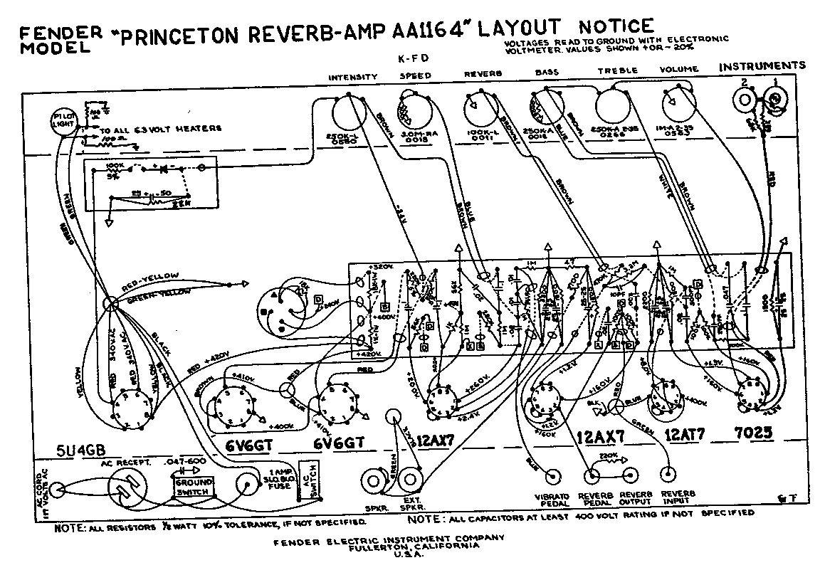
69 SFPR Schematic Telecaster Guitar
A 1969 Princeton Reverb amplifier is identified as utilizing the AA764 circuit design. Various online resources provide schematics for Fender amplifiers.
The Princeton Reverb amplifier, particularly the model from 1969, is renowned for its warm tone and versatile sound characteristics, making...
ELECTRICAL ENGINEERING TECHNOLOGY PROGRAM
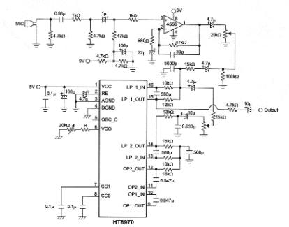
The objective of this project is to develop a multi-effect guitar processor capable of altering the tonal characteristics of a guitar. This device aims to provide a wide range of unique sounds, enhancing the entertainment value for users. The evolution...
Using tap potentiometer loudness circuit
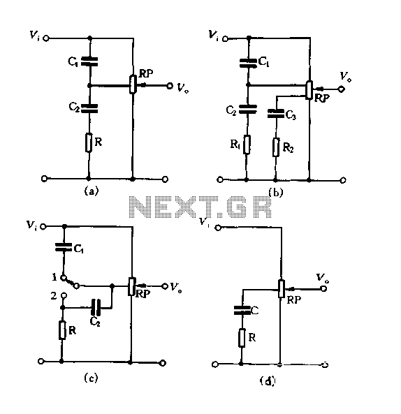
Figure 1.88 illustrates the loudness control circuit utilizing multiple taps on a potentiometer. In Figure (A), the connection is made between the tap and the potentiometer's input, along with the ground. An RC compensation network is employed, where the slide...
Guitar Tremolo Unit
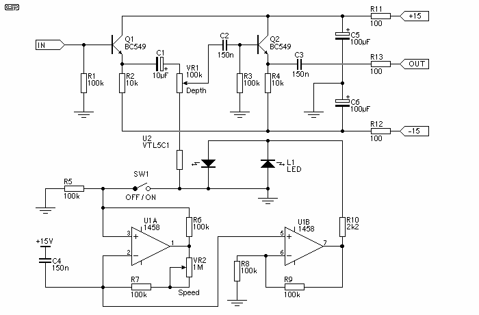
The unit is simple to build, and does not need really low noise opamps, since they only act as a modulator oscillator. I used 1458 dual types in the prototype, and they are more than good enough. The transistors can...
Guitar Vibrato circuit
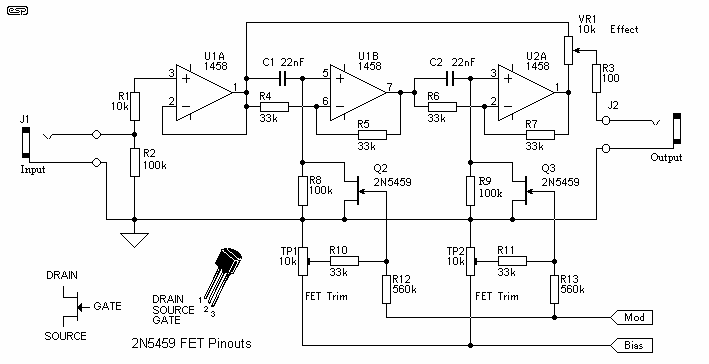
The circuit of the unit is fairly simple, but is a bit irksome to set up. The reason is that obtaining matched FETs is not easy, so I had to make sure that the circuit would work with off-the-shelf FETs....
Guitar Overdrive circuits
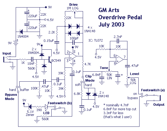
Although labelled as distortion, this is a soft clipping device, using germanium diodes. It's a good example of how little you need for a good basic sound. You could easily swap (or switch) these diodes to silicon types for hard...
Guitar Effect Bypass Circuit
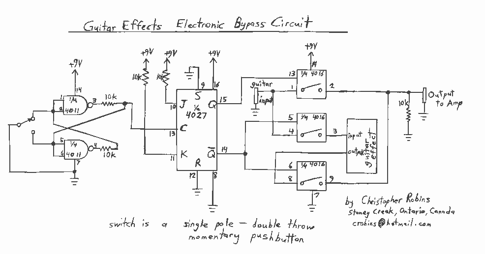
Observing my Boss pedals and how they were switched on and off I figured there must be more to it. It took me only about 4 hours to design and test this circuit. It works very well and I’m really...
Guitar Schematics
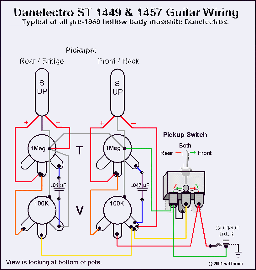
Using a magnetic compass, ensure that both pickups have a South polarity on the top of each pickup. Verify this by checking for a North polarity on the bottom of the pickups. It is uncommon to find both pickups with...
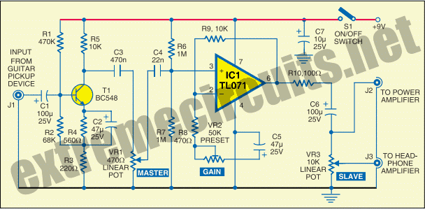
Electric Guitar Preamplifier
The circuit diagram of a guitar preamplifier is designed to accept any standard guitar pickup and features two signal outputs. A typical example of a pickup attached to a guitar headstock is illustrated. The pickup device consists of a transducer...