


car improvement automatic direction indicators
#direction indicators
#lane change
#automotive
#signal control
#vehicle safety
#motorway driving
#driver assistance
#flasher circuit
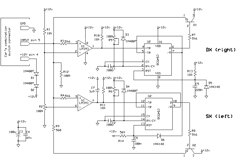
Description: Frequent use of direction indicators is essential for lane changes while driving on motorways. This is typically achieved by maintaining pressure on the indicator switch.
The operation of direction indicators, commonly known as turn signals, is crucial for safe driving, especially on high-speed roadways such as motorways. The direction indicator system consists of several key components: the indicator switch, the flasher unit, the bulb or LED indicators, and the vehicle's wiring harness.
The indicator switch is usually located on the steering column and is designed to be easily accessible to the driver. When the driver intends to change lanes, they activate the switch, which sends a signal to the flasher unit. The flasher unit is responsible for controlling the on-and-off blinking of the indicator lights, providing a visual cue to other drivers.
In modern vehicles, LED indicators are commonly used due to their energy efficiency and longer lifespan compared to traditional incandescent bulbs. The circuit design for the indicator system includes a relay that helps manage the current flow to the lights, ensuring they operate correctly without drawing excessive power from the vehicle's electrical system.
The wiring harness connects all components of the indicator system, routing power from the vehicle's battery to the flasher unit and the indicator lights. Proper insulation and protection of the wiring are essential to prevent short circuits and ensure reliable operation, especially in environments exposed to moisture and temperature variations.
In summary, the direction indicator system is a vital safety feature in vehicles, enhancing communication between drivers and promoting safer lane changes on motorways. Understanding the components and operation of this system is essential for effective vehicle maintenance and troubleshooting.As I often drive on motorways, I always and frequently use the direction indicators in order to show the lane change. I normally did this by holding a ..
The operation of direction indicators, commonly known as turn signals, is crucial for safe driving, especially on high-speed roadways such as motorways. The direction indicator system consists of several key components: the indicator switch, the flasher unit, the bulb or LED indicators, and the vehicle's wiring harness.
The indicator switch is usually located on the steering column and is designed to be easily accessible to the driver. When the driver intends to change lanes, they activate the switch, which sends a signal to the flasher unit. The flasher unit is responsible for controlling the on-and-off blinking of the indicator lights, providing a visual cue to other drivers.
In modern vehicles, LED indicators are commonly used due to their energy efficiency and longer lifespan compared to traditional incandescent bulbs. The circuit design for the indicator system includes a relay that helps manage the current flow to the lights, ensuring they operate correctly without drawing excessive power from the vehicle's electrical system.
The wiring harness connects all components of the indicator system, routing power from the vehicle's battery to the flasher unit and the indicator lights. Proper insulation and protection of the wiring are essential to prevent short circuits and ensure reliable operation, especially in environments exposed to moisture and temperature variations.
In summary, the direction indicator system is a vital safety feature in vehicles, enhancing communication between drivers and promoting safer lane changes on motorways. Understanding the components and operation of this system is essential for effective vehicle maintenance and troubleshooting.As I often drive on motorways, I always and frequently use the direction indicators in order to show the lane change. I normally did this by holding a ..

Voltage Regulator For Cars And Motorcycles
This regulator circuit can be used on an alternator that has one field terminal grounded. When the input voltage becomes too high, Q1 conducts, and the base of Q2 is driven toward ground, reducing the voltage fed to Q3. This...
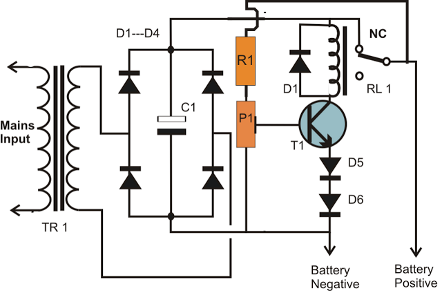
simplest smf automotive battery charger
A simple battery charger circuit is described, utilizing a single transistor for voltage detection and automatically disconnecting the battery from the supply when fully charged. The circuit's high voltage trip point is set to switch off the charging voltage when...
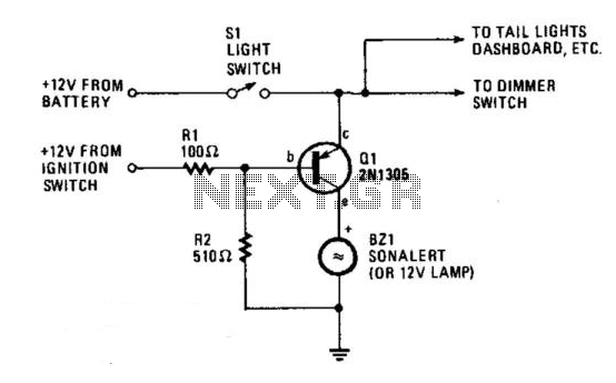
Automobile Lights-On Reminder
The circuit provides a visible or audible warning when the headlights are on. It utilizes a 2N1305 transistor as a switch to activate either a Sonalert tone generator or a small 12-V lamp. The operating current for the transistor is...
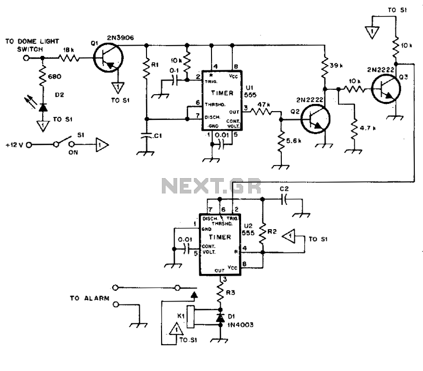
Automotive burglar alarm
The alarm activates after a 13-second delay and remains active for 1 to 1.5 minutes before automatically resetting. It can also be deactivated and reset by opening and reclosing switch SI.
The described circuit functions as a delay-triggered alarm system, incorporating...
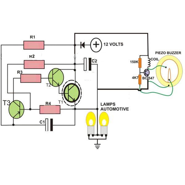
2-Pin Automobile Indicator Lamp Flasher Circuit with Buzzer
This circuit is designed to create a flasher unit for a motorbike. It is a simple turn signal flasher circuit that can be easily built and installed in any two-wheeler for the desired functionality. The circuit uses only two pins...
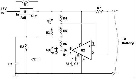
Car battery charger Automative car and motorcycle schematics
The circuit is designed to operate with an external power supply, which is why it does not include a transformer, rectifier, or filter capacitors in the schematic. However, these components can be added if desired. To utilize the circuit, connect...
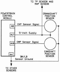
Camshaft Position Sensor
AutoZone Repair Guide for Engine Performance and Emission Control Components and Systems, specifically focusing on the Camshaft Position Sensor.
The Camshaft Position Sensor (CMP) is a critical component in modern internal combustion engines, playing a vital role in the management of...
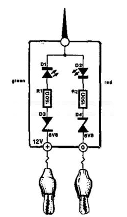
Automotive Electrical Tester
This compact tester is designed for checking vehicle electrical circuits. Two LEDs indicate whether one of the clips is connected to the positive supply line (red) or to ground (green). The unit is powered by the vehicle battery. It is...
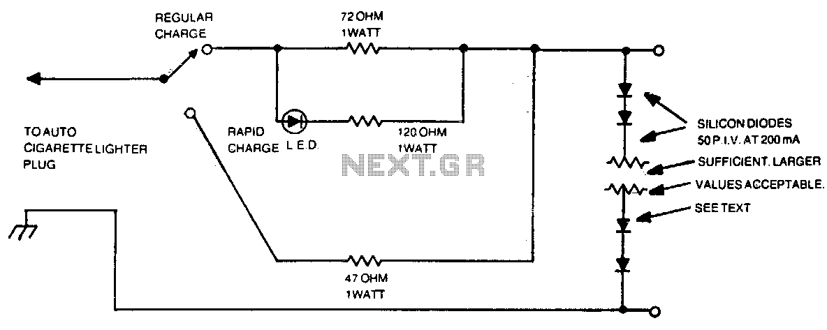
Automotive charger for ni-cad battery packs
The number of silicon diodes across the output is determined by the voltage of the battery pack. Each diode is considered at 0 volts. For example, a 10-volt pack would require 10/0 = 157, or 16 diodes.
In the context of...