


Electrical Systems and Circuits
#door locking system
#solenoid
#electric motor
#central locking
#driver door
#passenger door
#electro-mechanical
#vehicle security
#automotive electronics
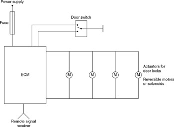
Description: A central door locking system allows all doors, including the boot lid or tailgate, to be locked centrally from the driver's door, typically including the front passenger's door as well. The locking and unlocking actions are performed by an electro-mechanical device, such as a solenoid or an electric motor. The door key activates a switch that controls the electrical supply to the door lock mechanism, while a remote control activates a switching circuit in the electronic control module (ECM), which also operates the locking mechanism. For safety and convenience, the interior door handles also engage the unlocking mechanism. The remote control functions similarly to a remote control for a domestic television, transmitting a unique code that is usually embedded in the ignition key. Two types of transmitters are utilized: infrared and radio frequency. The electronic control module (ECM) managing the current supply to the door lock actuators includes a sensor for detecting infrared signals or, in radio frequency systems, an aerial for receiving the radio frequency signal. The remote signal typically operates effectively over a range of several meters.
The central door locking system is a sophisticated assembly designed to enhance vehicle security and user convenience. It integrates several components, including an electronic control module (ECM), actuators, sensors, and transmitters. The ECM serves as the brain of the system, processing inputs from the door key switch and remote control, and managing the output to the locking mechanisms via the actuators.
The electro-mechanical devices, such as solenoids or electric motors, are responsible for the physical locking and unlocking of the doors. When the driver or passenger uses the key or remote control, the corresponding switch sends a signal to the ECM. The ECM then energizes the actuators, which engage or disengage the locking mechanism.
Remote controls utilize either infrared or radio frequency technologies to communicate with the ECM. Infrared systems require a direct line of sight between the remote and the ECM, while radio frequency systems allow for greater flexibility, enabling operation from various angles and distances. The unique code transmitted by the remote ensures that only the designated key can operate the locking system, preventing unauthorized access.
Interior door handles are designed to provide an additional layer of safety by allowing occupants to unlock the doors from inside the vehicle. This feature is critical in emergency situations, where quick access to exit the vehicle is necessary.
Overall, the central door locking system exemplifies modern automotive engineering, combining mechanical and electronic elements to provide a reliable and user-friendly solution for vehicle access and security.A central door locking system permits all doors, often including the boot lid or tailgate, to be locked centrally from the driver`s door and, normally includes the front passenger`s door also. The locking and unlocking action is produced by an electro-mechanical device, such as a solenoid or an electric motor.
The door key operates a switch which controls the electrical supply that actuates the door lock mechanism and the remote control activates a switching circuit in the electronic control module (ECM) that also actuates the locking mechanism. For safety and convenience, the interior door handles also operate the unlocking mechanism. The remote control operates in much the same way as the remote control for a domestic television. A unique code is transmitted from the remote control which is normally contained in the ignition key.
Two types of transmitter are used, infra-red and radio frequency. The electronic control module (ECM) that controls the supply of current to the door lock actuators contains a sensor that detects infra-red signals or, in the case of radio frequency systems, an aerial to detect the radio frequency signal. The remote signal is normally effective over a range of several metres. Figure. 12. 1 shows the general principle of central locking systems.
The central door locking system is a sophisticated assembly designed to enhance vehicle security and user convenience. It integrates several components, including an electronic control module (ECM), actuators, sensors, and transmitters. The ECM serves as the brain of the system, processing inputs from the door key switch and remote control, and managing the output to the locking mechanisms via the actuators.
The electro-mechanical devices, such as solenoids or electric motors, are responsible for the physical locking and unlocking of the doors. When the driver or passenger uses the key or remote control, the corresponding switch sends a signal to the ECM. The ECM then energizes the actuators, which engage or disengage the locking mechanism.
Remote controls utilize either infrared or radio frequency technologies to communicate with the ECM. Infrared systems require a direct line of sight between the remote and the ECM, while radio frequency systems allow for greater flexibility, enabling operation from various angles and distances. The unique code transmitted by the remote ensures that only the designated key can operate the locking system, preventing unauthorized access.
Interior door handles are designed to provide an additional layer of safety by allowing occupants to unlock the doors from inside the vehicle. This feature is critical in emergency situations, where quick access to exit the vehicle is necessary.
Overall, the central door locking system exemplifies modern automotive engineering, combining mechanical and electronic elements to provide a reliable and user-friendly solution for vehicle access and security.A central door locking system permits all doors, often including the boot lid or tailgate, to be locked centrally from the driver`s door and, normally includes the front passenger`s door also. The locking and unlocking action is produced by an electro-mechanical device, such as a solenoid or an electric motor.
The door key operates a switch which controls the electrical supply that actuates the door lock mechanism and the remote control activates a switching circuit in the electronic control module (ECM) that also actuates the locking mechanism. For safety and convenience, the interior door handles also operate the unlocking mechanism. The remote control operates in much the same way as the remote control for a domestic television. A unique code is transmitted from the remote control which is normally contained in the ignition key.
Two types of transmitter are used, infra-red and radio frequency. The electronic control module (ECM) that controls the supply of current to the door lock actuators contains a sensor that detects infra-red signals or, in the case of radio frequency systems, an aerial to detect the radio frequency signal. The remote signal is normally effective over a range of several metres. Figure. 12. 1 shows the general principle of central locking systems.
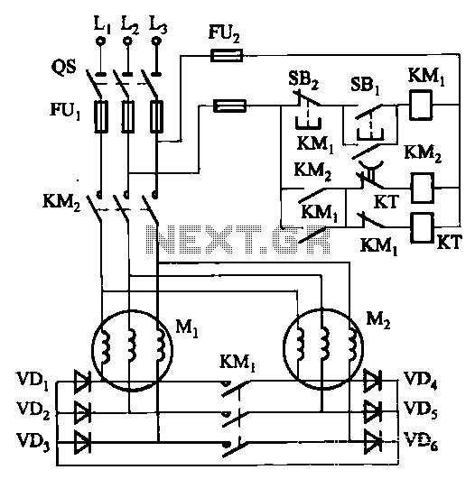
Two electric motors on the mechanical brake circuit
The circuit depicted in Figure 3-157 is designed for motors with a capacity of no more than 11 kW, requiring precise stopping capabilities. Upon shutdown, contact KMi releases, and the motor stator windings are configured into a three-phase rectifier circuit...
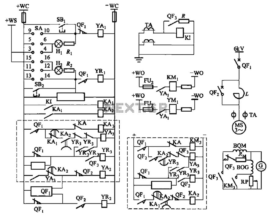
Synchronous electric motor chokes down according to the stator current excitation circuit
The circuit depicted in Figure 3-189 includes various components such as switch SA, closing button SBi, trip button SBz, de-excitation switch Yaa, and off trip coil YR3. The excitation switch contacts are represented by QF3, which serves as a circuit...
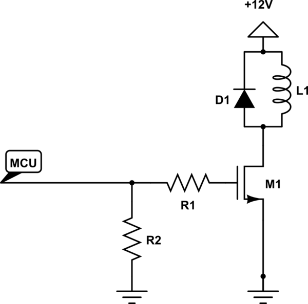
Solenoid Driving Circuit
The solenoid requires a specific amount of current to generate its magnetic field. If the solenoid were a perfect inductor, the DC current could rise excessively and potentially damage other circuit components. However, solenoids inherently possess a significant amount of...
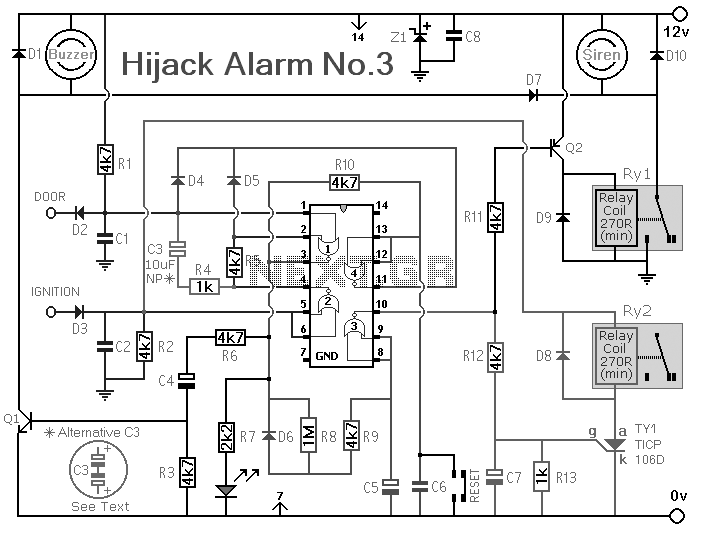
Vehicle Anti-Hijack Alarm No3
The Vehicle Anti-Hijack Alarm No3 is designed specifically for scenarios where a hijacker forcibly removes the driver from the vehicle. If any door is opened while the ignition is on, the circuit will activate.
The Vehicle Anti-Hijack Alarm No3 operates...
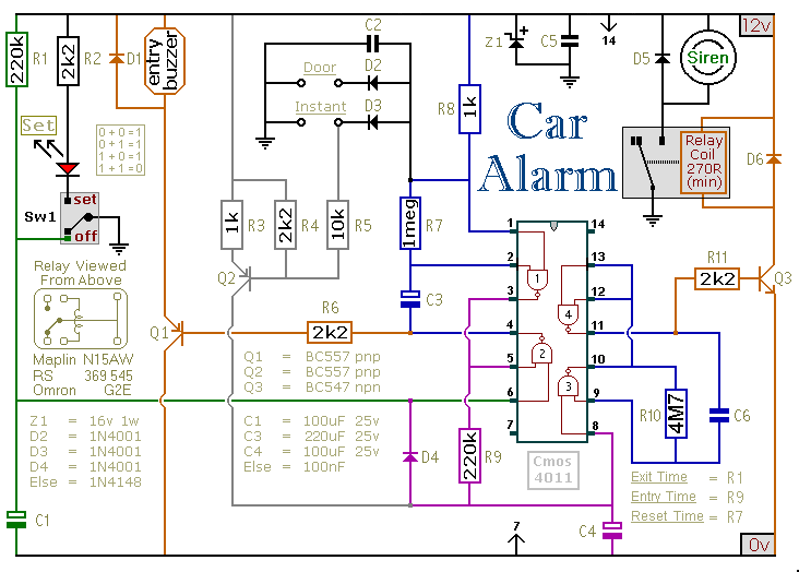
A Cmos Based Vehicle Anti-Theft Alarm circuit
This car alarm circuit includes exit and entry delays, an instant alarm zone, an intermittent siren output, and automatic reset. By incorporating external relays, it is possible to immobilize the vehicle and activate the flashing lights.
The car alarm circuit is...
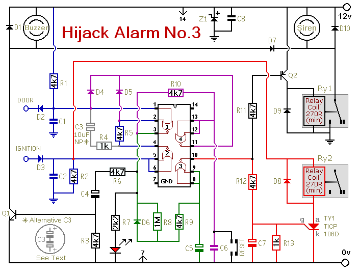
Vehicle Anti-Hijack Alarm No3 circuit
Similar to the initial two Hijack Alarms, this circuit is designed to activate if a door is opened while the ignition is switched on. After a delay of several minutes, allowing the thief to move a safe distance away, the...
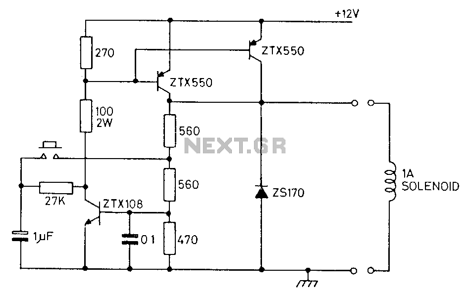
12V-latch
This circuit controls a solenoid using a single push-button switch. It is capable of supplying loads exceeding 1 A and can operate at a maximum speed of once every 0.6 seconds. Upon initial power application, the solenoid will always begin...

Pulse Operation of DC Solenoids
The solenoid operates with pulse action, receiving a brief surge of five to six times its rated voltage, followed by a holding voltage that is less than half of its rated voltage. This method significantly reduces application time, and the...
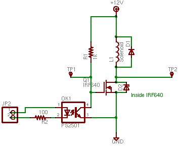
Solenoid Tutorial
Do not drive a solenoid directly from an Arduino. It requires more current than the Arduino can provide and can produce damaging voltages when switched off. A simple solution exists. The solenoid tested is a 12-volt solenoid, approximately the size...