


Synchronous electric motor chokes down according to the stator current excitation circuit
#electric motor
#stator current
#excitation circuit
#switch control
#magnetic switch
#de-excitation
#trip coil
#motor choke
#synchronous motor
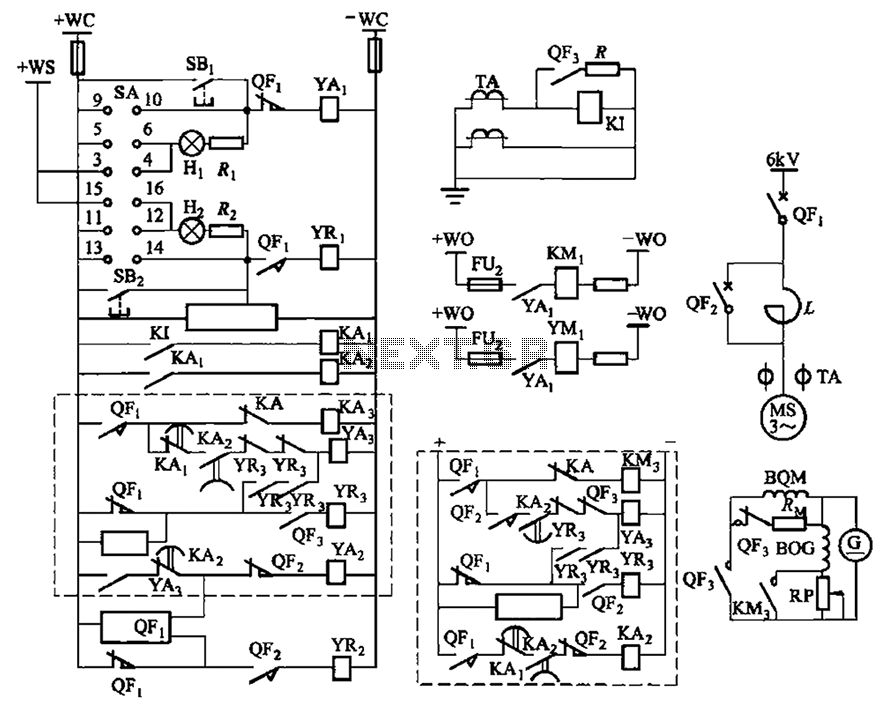
Description: The circuit depicted in Figure 3-189 includes various components such as switch SA, closing button SBi, trip button SBz, de-excitation switch Yaa, and off trip coil YR3. The excitation switch contacts are represented by QF3, which serves as a circuit breaker. The power synchronous motor is managed by circuit breaker QFi. At startup, circuit breaker QF2 is disconnected, and the synchronous motor is initiated through the reactance L, allowing for a step-down start until the motor reaches synchronous speed. Once the motor achieves this speed, closing circuit breaker QFz shorts reactor L, enabling the synchronous motor to operate at full pressure. When excitation switch QF3 is closed, the normally closed contacts disconnect the de-excitation circuit resistance RM, allowing the exciter to provide line excitation to the synchronous motor. When QFa trips, the exciter is removed from the synchronous motor field circuit, but the magnetoresistance RM will still affect the synchronous motor field circuit, leading to de-excitation. The size of the excitation current can be adjusted by changing the rheostat RP. Additionally, the marked virtual circuit represents a light box for starting the control circuit, while the labeled virtual circuit frame is intended for resuming the automatic control circuit.
The circuit in Figure 3-189 is designed to control a power synchronous motor using a combination of switches and circuit breakers that ensure safe and efficient operation. The main components include various switches for excitation and de-excitation, as well as circuit breakers that protect the system during operation.
At the initial stage, the synchronous motor is powered through a reactance (L) which allows for a gradual increase in speed, preventing sudden inrush currents that could damage the motor. Once the motor reaches synchronous speed, circuit breaker QFz is engaged to bypass the reactance, allowing the motor to operate under full voltage conditions, which is essential for optimal performance.
The excitation switch QF3 plays a critical role in managing the excitation current supplied to the motor. By closing this switch, the system disconnects the de-excitation resistance (RM), allowing the exciter to energize the motor's field winding. This process is crucial for maintaining the magnetic field necessary for the synchronous operation of the motor.
In the event of a fault or an overload condition, circuit breaker QFa is designed to trip, effectively removing the exciter from the motor field circuit. However, the configuration ensures that the magnetoresistance RM still influences the field circuit, facilitating a controlled de-excitation process rather than an abrupt shutdown, which could lead to mechanical stress on the motor.
The rheostat RP allows for fine-tuning of the excitation current, providing flexibility in the motor's performance characteristics. This adjustment capability is essential for applications requiring precise control over the motor's torque and speed.
The virtual circuits indicated in the schematic serve as visual aids for operators, providing a clear representation of the control mechanisms involved in starting and resuming the automatic control of the motor. This design enhances operational safety and efficiency, ensuring that the motor can be started and stopped without risk of damage or operational disruption. Circuit shown in Figure 3-189. Figure, SA controls switch; SBi is closing button; SBz to trip button; Yaa de-excitation switch is closing coil; YR3 is off trip coil magnetic sw itch; figure, for the excitation switch contacts QF3 each touch point. Excitation switch, a circuit breaker is made with the restructuring. Power synchronous motor is controlled by the circuit breaker QFi. When you start, disconnect breaker QF2, synchronous motor through the reactance L is step-down start until the motor reaches synchronous speed and quasi or more, closing the circuit breaker QFz shorting reactor L, the synchronous motor running at full pressure. When the excitation switch QF3 closing, the normally closed contacts disconnect de-excitation circuit resistance RM, exciter for synchronous motor into line excitation; when QFa trip exciter exits synchronous motor field circuit, but will destroy magnetoresistance RM access synchronous motor field circuit will be de-excitation.
Excitation current size can be changed by adjusting the rheostat RP. in graph. Marked virtual circuit is a light box to start the control circuit; labeled virtual circuit frame for the resumption of automatic control circuit.
The circuit in Figure 3-189 is designed to control a power synchronous motor using a combination of switches and circuit breakers that ensure safe and efficient operation. The main components include various switches for excitation and de-excitation, as well as circuit breakers that protect the system during operation.
At the initial stage, the synchronous motor is powered through a reactance (L) which allows for a gradual increase in speed, preventing sudden inrush currents that could damage the motor. Once the motor reaches synchronous speed, circuit breaker QFz is engaged to bypass the reactance, allowing the motor to operate under full voltage conditions, which is essential for optimal performance.
The excitation switch QF3 plays a critical role in managing the excitation current supplied to the motor. By closing this switch, the system disconnects the de-excitation resistance (RM), allowing the exciter to energize the motor's field winding. This process is crucial for maintaining the magnetic field necessary for the synchronous operation of the motor.
In the event of a fault or an overload condition, circuit breaker QFa is designed to trip, effectively removing the exciter from the motor field circuit. However, the configuration ensures that the magnetoresistance RM still influences the field circuit, facilitating a controlled de-excitation process rather than an abrupt shutdown, which could lead to mechanical stress on the motor.
The rheostat RP allows for fine-tuning of the excitation current, providing flexibility in the motor's performance characteristics. This adjustment capability is essential for applications requiring precise control over the motor's torque and speed.
The virtual circuits indicated in the schematic serve as visual aids for operators, providing a clear representation of the control mechanisms involved in starting and resuming the automatic control of the motor. This design enhances operational safety and efficiency, ensuring that the motor can be started and stopped without risk of damage or operational disruption. Circuit shown in Figure 3-189. Figure, SA controls switch; SBi is closing button; SBz to trip button; Yaa de-excitation switch is closing coil; YR3 is off trip coil magnetic sw itch; figure, for the excitation switch contacts QF3 each touch point. Excitation switch, a circuit breaker is made with the restructuring. Power synchronous motor is controlled by the circuit breaker QFi. When you start, disconnect breaker QF2, synchronous motor through the reactance L is step-down start until the motor reaches synchronous speed and quasi or more, closing the circuit breaker QFz shorting reactor L, the synchronous motor running at full pressure. When the excitation switch QF3 closing, the normally closed contacts disconnect de-excitation circuit resistance RM, exciter for synchronous motor into line excitation; when QFa trip exciter exits synchronous motor field circuit, but will destroy magnetoresistance RM access synchronous motor field circuit will be de-excitation.
Excitation current size can be changed by adjusting the rheostat RP. in graph. Marked virtual circuit is a light box to start the control circuit; labeled virtual circuit frame for the resumption of automatic control circuit.
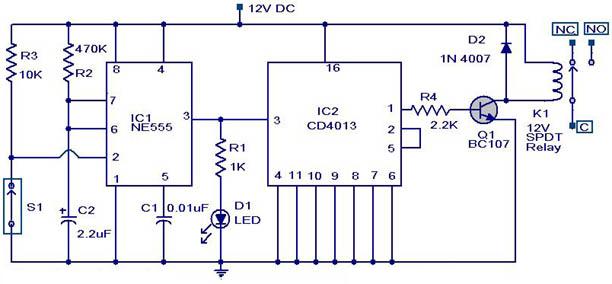
magnetic switch circuit
A magnetic switch is a circuit designed to respond to surrounding magnetic fields detected by the sensor. This series of magnetic switches employs limit switch sensors that include an additional metal plate capable of responding to a magnet. The magnetic...
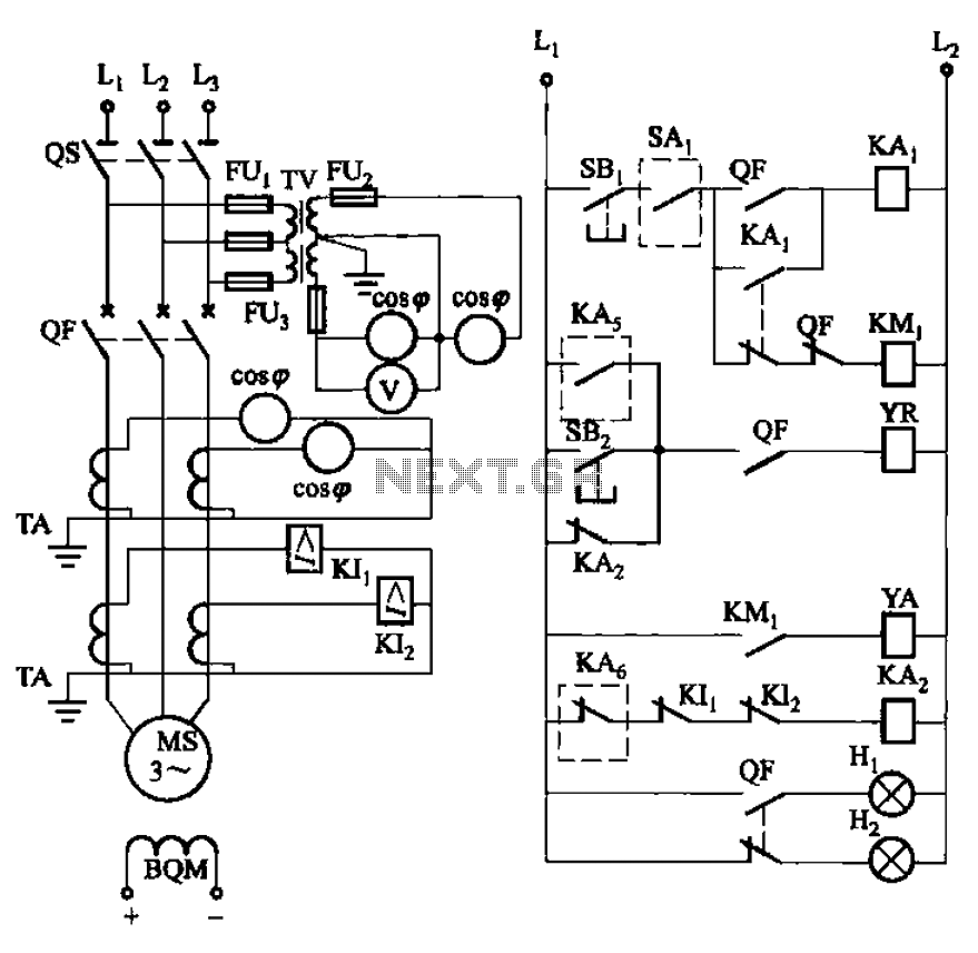
Synchronous motor full voltage start-up circuit
The circuit depicted in Figure 3-186 includes an isolation switch, QF vacuum circuit breakers, YR line for the circuit breaker coil, and YA for the circuit breaker closing coil. Additionally, there is a dashed box representing the excitation device (not...
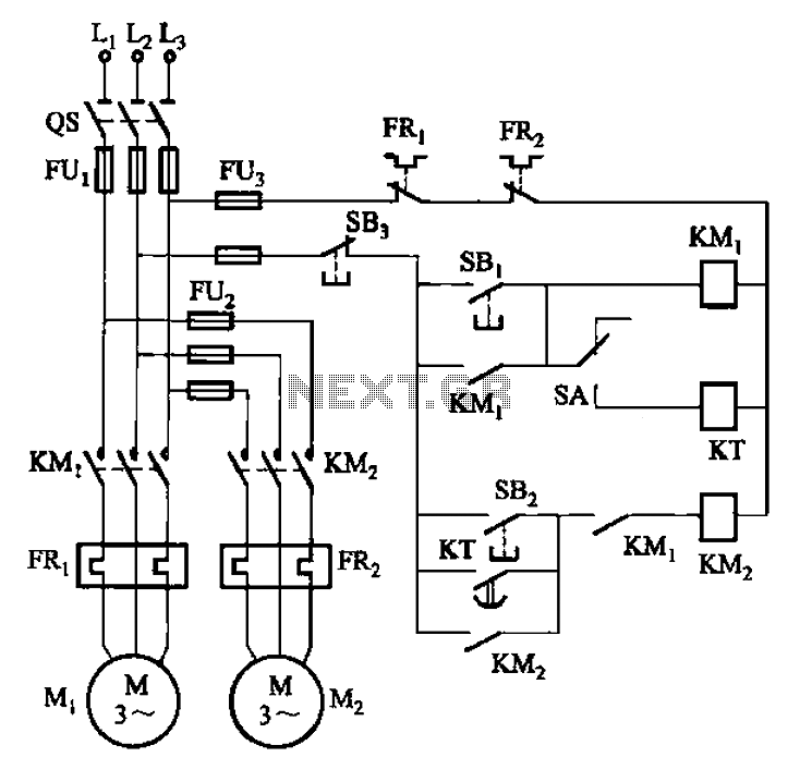
Two electric motors has started manual and automatic control circuit
The circuit illustrated in Figure 3-85 features both manual and automatic control through the transfer switch SA. After initiating the motor Mi, an automatic start sequence is achieved via the time relay KT.
The circuit employs a transfer switch (SA) that...
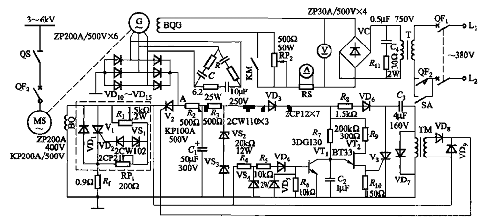
One synchronous motor thyristor excitation circuit
The circuit depicted in Figure 16-105 illustrates a synchronous motor. The components include BQ, which represents its field winding, and G, which denotes the AC excitation for the motor. The notation BQG indicates the field winding, with an empty box...
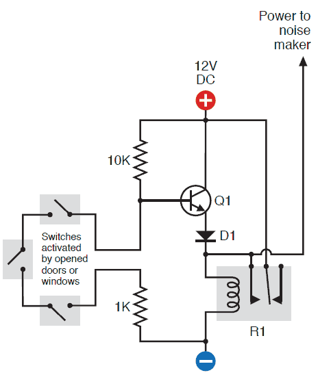
magnetic switch activated alarm
A circuit was assembled on a breadboard, which is divided into two sections. The right section is dedicated to generating a wailing alarm, while the left section is...
The circuit design comprises two main functional blocks: the alarm generation circuit and...
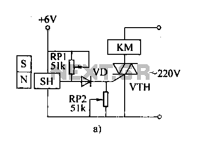
Magneto circuit diagram of a remote control switch
The automatic weapon features a magnetic switch circuit that is simple, reliable, has a low failure rate, and offers good versatility. It can be used for output performance or converted into mechanical displacement applications. The circuit diagram utilizes a Hall...
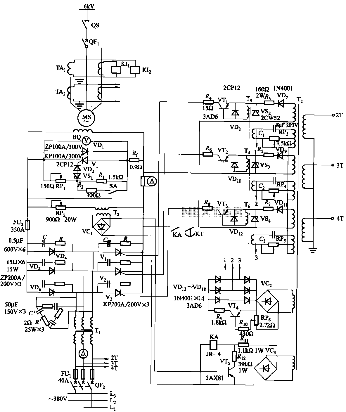
Synchronous motor thyristor excitation circuit
The excitation device for a light-duty synchronous motor rated at 625 kW has been initiated. The triggering circuit of the device consists of three identical RC phase-shift flip-flops. Adjustment potentiometers RP3 to RPs are used to set the RC phase...
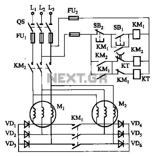
Two electric motors on the mechanical brake circuit
The circuit depicted in Figure 3-157 is designed for motors with a capacity of no more than 11 kW, requiring precise stopping capabilities. Upon shutdown, contact KMi releases, and the motor stator windings are configured into a three-phase rectifier circuit...
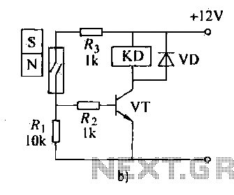
Magneto Remote control switch circuit diagram
The automatic weapon features a magnetic switch circuit that is simple, reliable, has a low failure rate, and offers good versatility. It can be used to output performance or convert mechanical displacement. The circuit diagram utilizes a Hall switch (SH)...