


I ran a code on my 99 dodge ram 1500 and it came back with
#voltmeter
#ignition
#engine
#distributor
#diagnostics
#Dodge Ram
#paper clips
#connector
#analog measurement
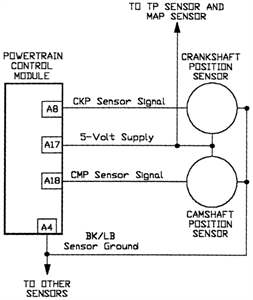
Description: For this test, an analog (non-digital) voltmeter is required. The distributor connector must remain intact. Small paper clips should be inserted into the backside of the distributor wire harness connector to establish contact with the terminals without damaging the connector. The voltmeter leads should then be attached to these clips. With the ignition turned ON, the engine should be rotated. The meter should display a reading of less than 1 volt and a maximum reading of 5.0 volts as the high and low points on the wheel pass the sensor. If 5.0 volts is not detected at the supply wire, voltage should be checked at cavity A-17 of the 32-way connector, ensuring the engine controller harness remains connected during this test. If voltage is absent at the PCM connector, system diagnostics should be performed using a DRBII scan tool or equivalent, or the vehicle should be taken to a qualified repair shop. Continuity should be checked between the sensor and supply wire, specifically between the distributor connector and cavity A-17. If continuity is lacking, the wire harness requires repair. Additionally, continuity should be verified between the camshaft position sensor output wire and cavity A-18 at the engine controller. If this continuity is not present, the wire harness must also be repaired. While cranking the engine, the voltmeter should indicate fluctuations between 0 and 5 volts, which will confirm that the camshaft position sensor is functioning correctly and generating a sync pulse signal.
The circuit testing procedure described involves the use of an analog voltmeter to assess the functionality of the camshaft position sensor within an automotive system. This test is critical for ensuring accurate engine timing and synchronization, which are essential for optimal engine performance.
The analog voltmeter provides real-time voltage readings that reflect the operation of the camshaft position sensor as the engine is cranked. The use of paper clips to access the distributor connector terminals allows for a non-invasive method of measuring voltage without disconnecting the harness, thereby preserving the integrity of the connections.
During the test, a voltage reading below 1 volt indicates that the sensor is not triggering, while a peak reading of 5.0 volts confirms that the sensor is active and responding to the high and low points of the wheel. If the expected voltage levels are not observed, further diagnostics are necessary. Checking the voltage at cavity A-17 of the 32-way connector serves as a troubleshooting step to ensure that power is reaching the sensor from the engine controller.
Continuity tests between the distributor connector and the specified cavities in the engine controller are essential to identify any breaks or faults in the wiring that could impede the sensor's operation. The requirement for a DRBII scan tool or equivalent for further diagnostics emphasizes the complexity of modern automotive electronics, where precise communication between components is vital for system functionality.
In conclusion, this test not only verifies the operational status of the camshaft position sensor but also highlights the importance of maintaining proper electrical connections within the vehicle's wiring harness. Ensuring continuity and voltage levels are within specified ranges is crucial for diagnosing potential issues that could affect engine performance and reliability.For this test you will need an analog (non-digital) voltmeter. Do NOT remove the distributor connector. Using small paper clips, insert them into the backside of the distributor wire harness connector to make contact with the terminals. Do NOT damage the connector when inserting the paper clips. Attach the voltmeter leads to these clips. Turn the ignition ON. Rotate the engine. The meter should show a reading of less than 1 volt and a high voltage reading of 5. 0 volts as the high and low points on the wheel pass the sensor. If 5. 0 volts is not found at the supply wire, check for voltage at cavity A-17 of the 32-way connector. Leave the engine controller harness connected for this test. NOTE If voltage is not found at the PCM connector, you will need to diagnose the system using a DRBII scan tool, or equivalent, or take the vehicle to a qualified shop. Check continuity between the sensor and supply wire. This is checked between the distributor connector and cavity A-17. If continuity is not present, repair the wire harness. Check for continuity between the camshaft position sensor output wire and cavity A-18 at the engine controller.
If continuity is not present, repair the wire harness. Crank the engine while observing the voltmeter. The voltmeter needle should fluctuate 0-5 volts, approximately. This will verify the camshaft position sensor is operating properly and a sync pulse signal is being generated.
The circuit testing procedure described involves the use of an analog voltmeter to assess the functionality of the camshaft position sensor within an automotive system. This test is critical for ensuring accurate engine timing and synchronization, which are essential for optimal engine performance.
The analog voltmeter provides real-time voltage readings that reflect the operation of the camshaft position sensor as the engine is cranked. The use of paper clips to access the distributor connector terminals allows for a non-invasive method of measuring voltage without disconnecting the harness, thereby preserving the integrity of the connections.
During the test, a voltage reading below 1 volt indicates that the sensor is not triggering, while a peak reading of 5.0 volts confirms that the sensor is active and responding to the high and low points of the wheel. If the expected voltage levels are not observed, further diagnostics are necessary. Checking the voltage at cavity A-17 of the 32-way connector serves as a troubleshooting step to ensure that power is reaching the sensor from the engine controller.
Continuity tests between the distributor connector and the specified cavities in the engine controller are essential to identify any breaks or faults in the wiring that could impede the sensor's operation. The requirement for a DRBII scan tool or equivalent for further diagnostics emphasizes the complexity of modern automotive electronics, where precise communication between components is vital for system functionality.
In conclusion, this test not only verifies the operational status of the camshaft position sensor but also highlights the importance of maintaining proper electrical connections within the vehicle's wiring harness. Ensuring continuity and voltage levels are within specified ranges is crucial for diagnosing potential issues that could affect engine performance and reliability.For this test you will need an analog (non-digital) voltmeter. Do NOT remove the distributor connector. Using small paper clips, insert them into the backside of the distributor wire harness connector to make contact with the terminals. Do NOT damage the connector when inserting the paper clips. Attach the voltmeter leads to these clips. Turn the ignition ON. Rotate the engine. The meter should show a reading of less than 1 volt and a high voltage reading of 5. 0 volts as the high and low points on the wheel pass the sensor. If 5. 0 volts is not found at the supply wire, check for voltage at cavity A-17 of the 32-way connector. Leave the engine controller harness connected for this test. NOTE If voltage is not found at the PCM connector, you will need to diagnose the system using a DRBII scan tool, or equivalent, or take the vehicle to a qualified shop. Check continuity between the sensor and supply wire. This is checked between the distributor connector and cavity A-17. If continuity is not present, repair the wire harness. Check for continuity between the camshaft position sensor output wire and cavity A-18 at the engine controller.
If continuity is not present, repair the wire harness. Crank the engine while observing the voltmeter. The voltmeter needle should fluctuate 0-5 volts, approximately. This will verify the camshaft position sensor is operating properly and a sync pulse signal is being generated.
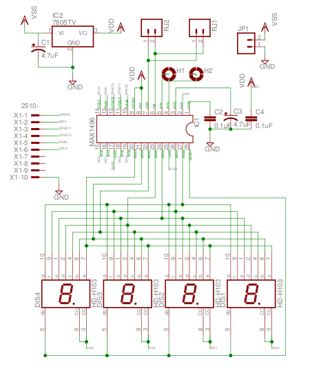
Simple Voltmeter schematic using Maxims ADC with LED driver
The MAX1496 is an analog-to-digital converter (ADC) that incorporates LED drivers, allowing for the construction of a 3 1/2 digit voltmeter using a minimal number of components. This device features both external and internal voltage reference options, along with HOLD...
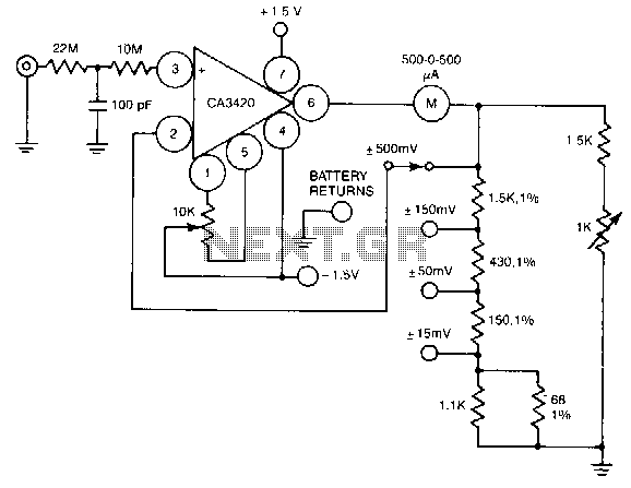
High-input-resistance-voltmeter
A resistance of 1,000,000 MΩ takes advantage of the high input impedance of the CA3420 BiMOS op-amp. Only two 1.5-V AA-type penlite batteries are required for use. Full-scale deflection is ±500 nV, ±150 mV, and ±15 mV.
The circuit utilizes a...
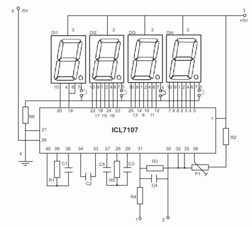
Led display digital Voltmeter
The copyright of this circuit is owned by Smart Kit Electronics. This document discusses improvements and modifications based on the original schematic. It describes a straightforward yet highly accurate and useful digital voltmeter designed as a panel meter, suitable for...
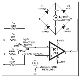
universal high resistance voltmeter
The full-scale deflection of the universal high-input-resistance voltmeter circuit depends on the position of the function switch. The term IFS in the equations refers to the meter's full-scale deflection current rating in amperes. It is important to note that neither...
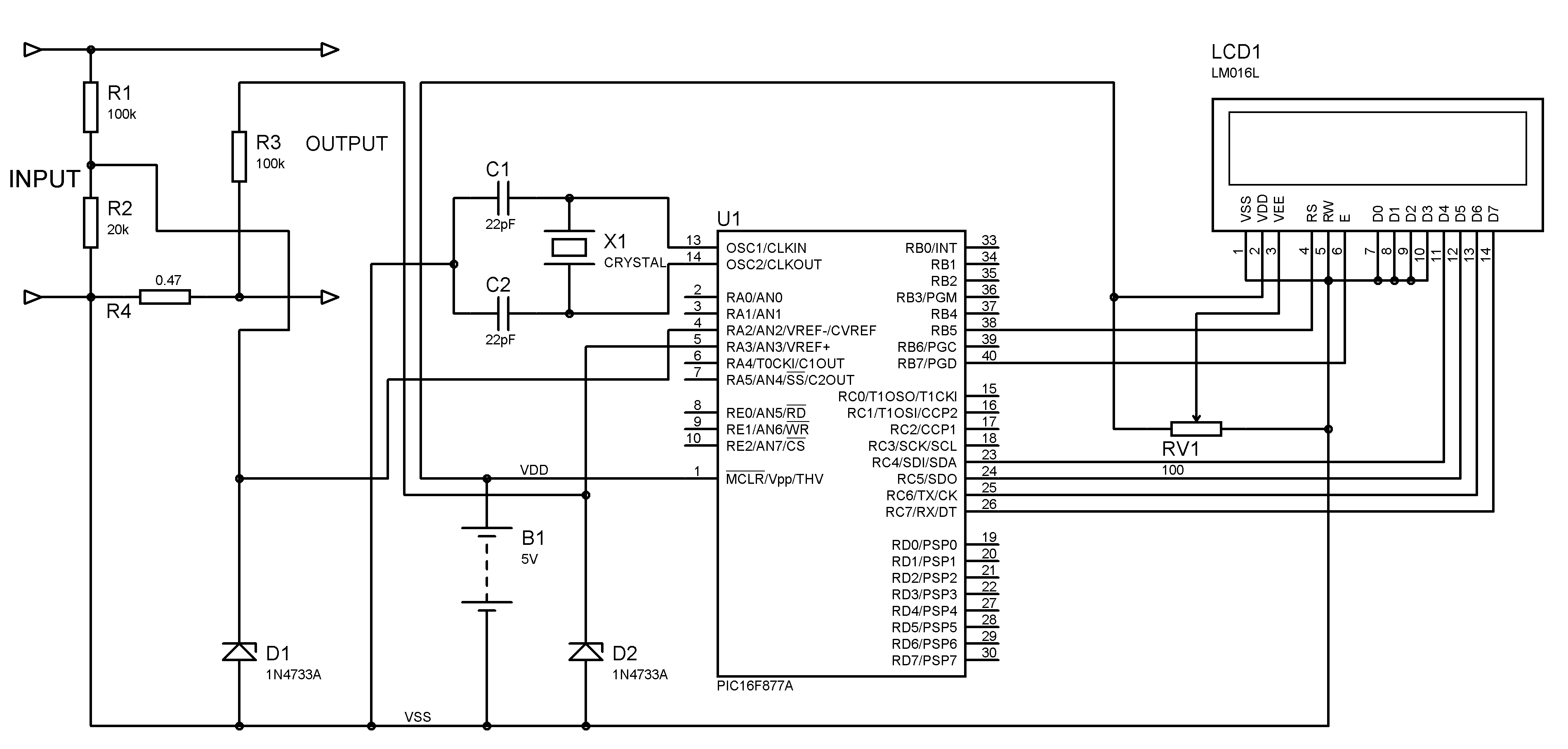
voltmeter ammeter pic
A voltmeter and ammeter can be constructed using a PIC microcontroller equipped with an Analog to Digital Converter (ADC). The project utilizes the PIC16F877A microcontroller, with results displayed on an LCD. This microcontroller is sufficient for testing purposes. For a...
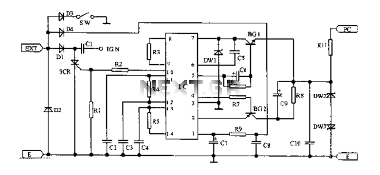
125 Motorcycle electronic ignition circuit diagram
An AC magneto is connected to an external circuit. The output is rectified by diode D1 and stored in capacitor C1. Additional rectification is performed by diodes D4, along with resistors R9 and capacitors C7 and C8, which filter the...
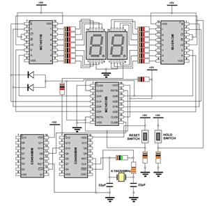
digital voltmeter circuit diagram
The WPG DM8168 DaVinci high-definition video System on Chip (SoC) offers multiple DVR/NVR surveillance solutions, utilizing the MT9M033 image sensor as a key component in safety monitoring systems. This solution is complemented by Conexant's line of multi-channel video surveillance applications,...
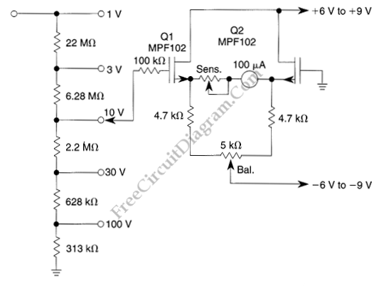
Low-Drift High-Impedance JFET DC Voltmeter
The voltmeter illustrated in the schematic diagram below possesses a very high input impedance. The range selector employs standard voltage divider resistors; however, due to the subsequent preamplifier utilizing JFETs, the divider can be designed with very high resistance series...
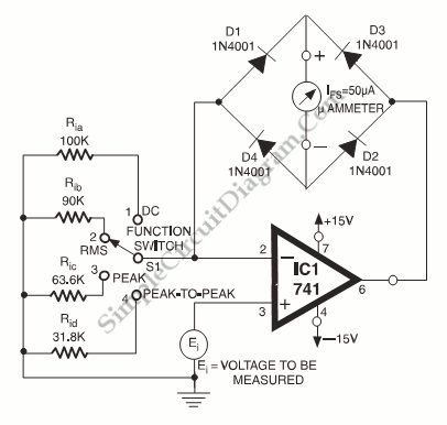
DC RMS And Peak-to-Peak High Impedance Voltmeter
An analog meter typically does not exhibit high impedance due to the absence of a buffer circuit within its design. By incorporating active buffering, the input impedance of this circuit can be significantly enhanced.
The integration of an active buffer circuit...