


Jeep Grand Cherokee Brake Light Woes
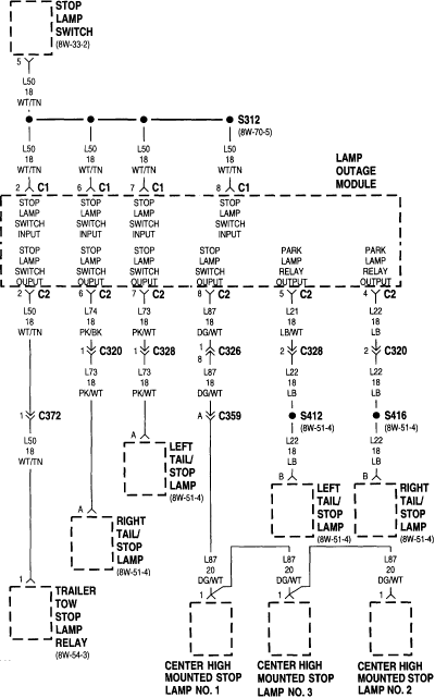
Description: Auto repair questions concerning brake light issues for the Jeep Grand Cherokee.
The Jeep Grand Cherokee features a complex electrical system that integrates various components responsible for the operation of the brake lights. When troubleshooting brake light problems, it is essential to consider several factors, including the brake light switch, wiring integrity, and the bulbs themselves.
The brake light switch is typically located near the brake pedal and is responsible for completing the circuit that activates the brake lights when the pedal is pressed. A malfunctioning switch can prevent the lights from illuminating. Testing the switch for continuity with a multimeter can help determine if it is functioning correctly.
Wiring issues may also contribute to brake light failures. Inspecting the wiring harness for any signs of wear, damage, or corrosion is crucial. Loose connections or frayed wires can interrupt the electrical flow, leading to non-functional brake lights.
Additionally, the bulbs should be checked to ensure they are not burned out. Replacing faulty bulbs is a straightforward task that can often resolve brake light issues.
In some cases, the problem may be related to the vehicle's body control module (BCM), which manages the electrical systems. If all other components check out, diagnostic tools may be necessary to assess the BCM's functionality.
Overall, a systematic approach to diagnosing brake light issues in a Jeep Grand Cherokee involves checking the brake light switch, inspecting wiring and connections, and testing the bulbs, with consideration given to the BCM if necessary.Auto Repair Question Answered for Jeep Grand Cherokee Brake Light Woes.
The Jeep Grand Cherokee features a complex electrical system that integrates various components responsible for the operation of the brake lights. When troubleshooting brake light problems, it is essential to consider several factors, including the brake light switch, wiring integrity, and the bulbs themselves.
The brake light switch is typically located near the brake pedal and is responsible for completing the circuit that activates the brake lights when the pedal is pressed. A malfunctioning switch can prevent the lights from illuminating. Testing the switch for continuity with a multimeter can help determine if it is functioning correctly.
Wiring issues may also contribute to brake light failures. Inspecting the wiring harness for any signs of wear, damage, or corrosion is crucial. Loose connections or frayed wires can interrupt the electrical flow, leading to non-functional brake lights.
Additionally, the bulbs should be checked to ensure they are not burned out. Replacing faulty bulbs is a straightforward task that can often resolve brake light issues.
In some cases, the problem may be related to the vehicle's body control module (BCM), which manages the electrical systems. If all other components check out, diagnostic tools may be necessary to assess the BCM's functionality.
Overall, a systematic approach to diagnosing brake light issues in a Jeep Grand Cherokee involves checking the brake light switch, inspecting wiring and connections, and testing the bulbs, with consideration given to the BCM if necessary.Auto Repair Question Answered for Jeep Grand Cherokee Brake Light Woes.

Brake Light Signal Module
Circuits of this type are designed to drive LED arrays to enhance visibility and conspicuity when a vehicle is stopped or slowing down. This specific circuit emits a visual alert signal consisting of four short flashes followed by a steady...
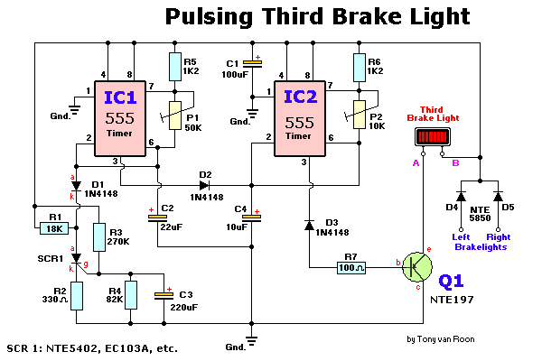
Pulsing Third Brake Light Circuit
Any type of flashing light on the main brake lights is prohibited and illegal in most states of the U.S.A. Verification is being conducted for the same in Canada. Meanwhile, using this circuit is at one's own risk, with awareness...

Voltage Regulator For Cars And Motorcycles
This regulator circuit can be used on an alternator that has one field terminal grounded. When the input voltage becomes too high, Q1 conducts, and the base of Q2 is driven toward ground, reducing the voltage fed to Q3. This...
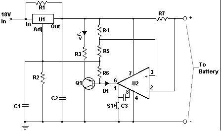
Car battery charger Automative car and motorcycle schematics
The circuit is designed to operate with an external power supply, which is why it does not include a transformer, rectifier, or filter capacitors in the schematic. However, these components can be added if desired. To utilize the circuit, connect...
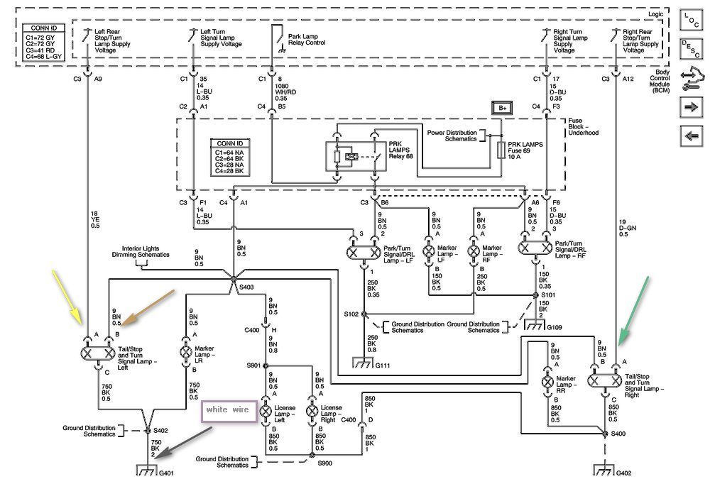
running lights brake light to work but not the turn signal harness
The left side of the vehicle operates correctly, with the running lights and brake light functioning properly. However, the turn signal is not working when wired directly into the harness. There is a preference to avoid purchasing a plug-in harness...
Delayed-extra-brake-light
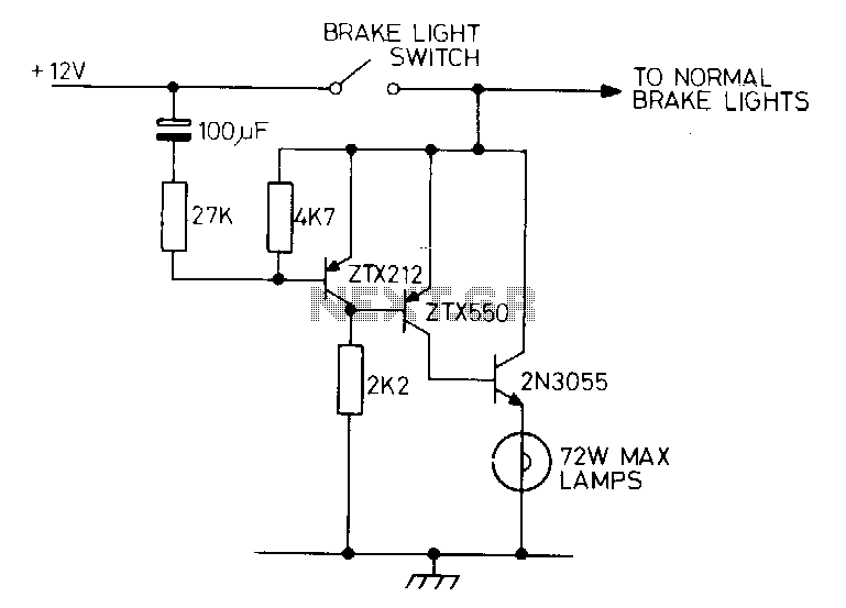
Activating the brake pedal in a vehicle triggers the standard brake lights, followed by a delay before the additional lights are illuminated. A bimetal strip connected in series with the lights can create a flashing effect.
The described circuit operates on...
1999 Jeep Grand Cherokee Gauges shutoff
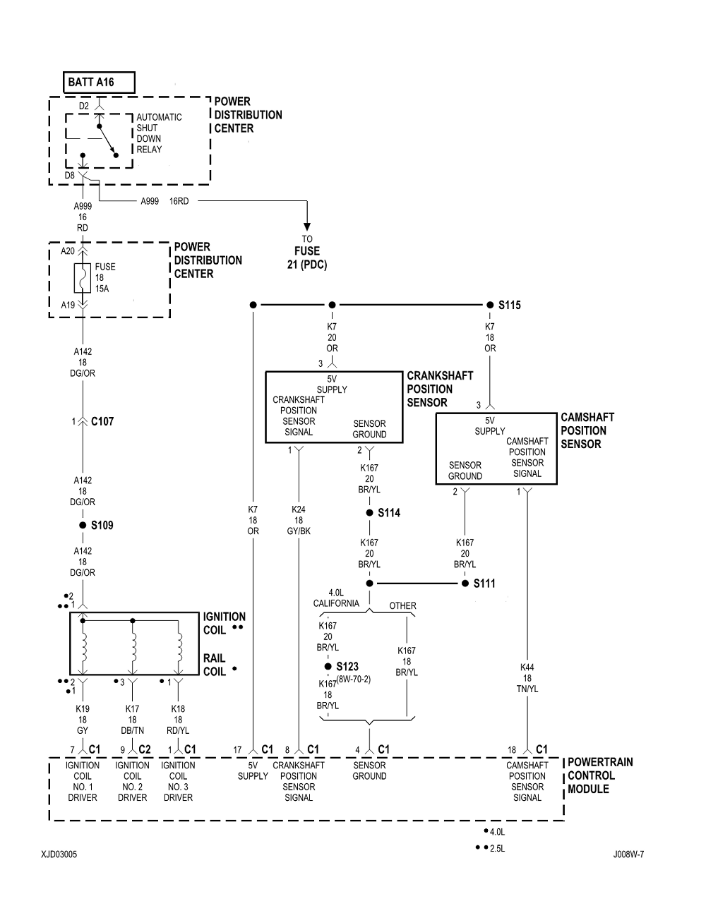
While driving the car, the gauges turn off and the car stalls immediately. The car will not start until the gauges come back on. When the gauges are off, the car starter will turn over the engine, but it will...
HIGHWAY ALERT SIGNAL LAMP
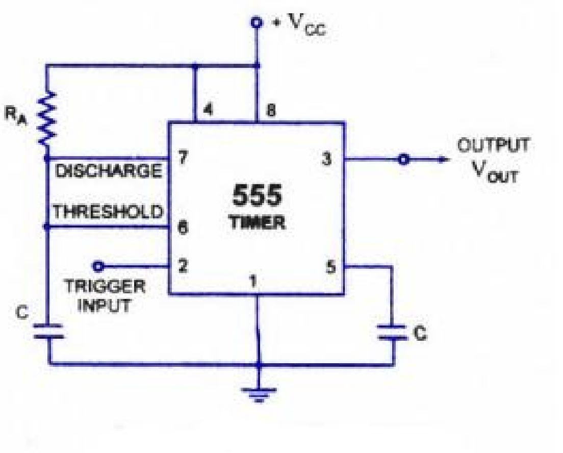
The lighting system of a motor vehicle comprises lighting and signaling devices mounted or integrated at the front, sides, rear, and sometimes the top of the vehicle. This system's purpose is to provide illumination for the driver to operate the...
Third Brake Light
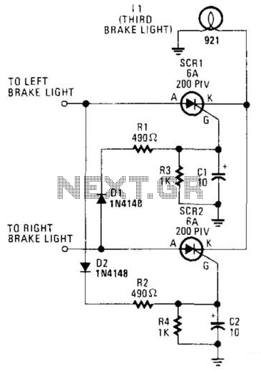
The circuit is designed to illuminate the third brake light (via SCR1 and SCR2) only when both the left and right brake lights are activated. The circuit operates on 12-V negative-ground systems. When the brake pedal is depressed, 12 V...