


The schematic diagram fo Car Horn using IC 555
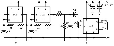
Description: The following diagram is the schematic diagram for a car horn circuit, which can be utilized for car modifications. Components List: R1 = 68K, R2 = 2K2, R3 = 56K, R4 = 3K3, R5, R6 = 4K7, R7 = 10K Pot/trimpot, C1, C2 = 22nF, C3, C5 = 100nF, C4 = 1nF, C6 = 22.
The car horn circuit schematic is designed to integrate various resistive and capacitive components to control the sound output of the horn. The circuit utilizes a combination of resistors (R1 to R7) and capacitors (C1 to C6) to shape the audio signal, ensuring that the horn produces a distinct sound that is suitable for automotive applications.
Resistors R1 (68K), R2 (2K2), R3 (56K), and R4 (3K3) serve to limit current flow and set the gain of the signal. R5 and R6, both rated at 4K7, are used for biasing purposes, while R7, a 10K potentiometer, allows for adjustable control over the circuit, enabling fine-tuning of the horn's volume or pitch.
The capacitors play a crucial role in filtering and coupling within the circuit. C1 and C2, each with a capacitance of 22nF, are likely used for high-frequency signal coupling, while C3 and C5, rated at 100nF, can serve as decoupling capacitors to stabilize the power supply and prevent noise. C4, with a value of 1nF, may be utilized for high-pass filtering, and C6 (22nF) further assists in signal processing.
This schematic is ideal for those looking to modify or enhance their vehicle's horn system, providing a clear and effective means to achieve desired sound characteristics through careful component selection and arrangement. Proper implementation of this circuit will ensure reliable operation and improved auditory signaling for automotive applications.The following diagram is the schematic diagram fo Car Horn, you may try this circuit for your car modification Components List: R1 = 68K R2 = 2K2 R3 = 56K R4 = 3K3 R5,R6 = 4K7 R7 = 10K Pot/trimpot C1,C2 = 22nF C3,C5 = 100nF C4 = 1nF C6 = 22..
The car horn circuit schematic is designed to integrate various resistive and capacitive components to control the sound output of the horn. The circuit utilizes a combination of resistors (R1 to R7) and capacitors (C1 to C6) to shape the audio signal, ensuring that the horn produces a distinct sound that is suitable for automotive applications.
Resistors R1 (68K), R2 (2K2), R3 (56K), and R4 (3K3) serve to limit current flow and set the gain of the signal. R5 and R6, both rated at 4K7, are used for biasing purposes, while R7, a 10K potentiometer, allows for adjustable control over the circuit, enabling fine-tuning of the horn's volume or pitch.
The capacitors play a crucial role in filtering and coupling within the circuit. C1 and C2, each with a capacitance of 22nF, are likely used for high-frequency signal coupling, while C3 and C5, rated at 100nF, can serve as decoupling capacitors to stabilize the power supply and prevent noise. C4, with a value of 1nF, may be utilized for high-pass filtering, and C6 (22nF) further assists in signal processing.
This schematic is ideal for those looking to modify or enhance their vehicle's horn system, providing a clear and effective means to achieve desired sound characteristics through careful component selection and arrangement. Proper implementation of this circuit will ensure reliable operation and improved auditory signaling for automotive applications.The following diagram is the schematic diagram fo Car Horn, you may try this circuit for your car modification Components List: R1 = 68K R2 = 2K2 R3 = 56K R4 = 3K3 R5,R6 = 4K7 R7 = 10K Pot/trimpot C1,C2 = 22nF C3,C5 = 100nF C4 = 1nF C6 = 22..
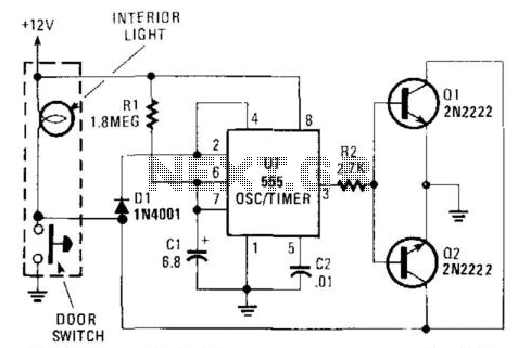
Interior Convenience Light
When the door is closed, this circuit maintains the dome light illumination for a duration determined by the values of R1 and C1. The approximate time is given by the equation (1.1)R1 x C1.
The described circuit functions as a timer...
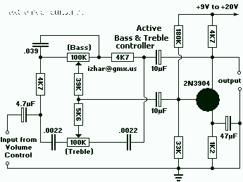
Bass and Tremble Controller
It is very useful for 1 -100 watt AUDIO AMPLIFIERS
This description refers to a component or circuit designed to enhance the performance of audio amplifiers in the power range of 1 to 100 watts. Such amplifiers are commonly used in...
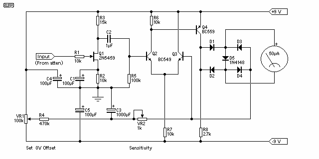
Audio Millivoltmeter
An AC millivoltmeter - calibrated in dB - with a range of 30V down to 3mV full scale (80dB range) would be extremely useful. Attach a microphone (electret mic capsules are quite good), and you have a relative sound level...
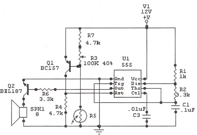
IC 555 Light Alarm
The IC 555 Light Alarm (Sun Up Alarm) is a circuit designed to emit a loud alarm at dawn, particularly beneficial for individuals who struggle to wake up even with a traditional alarm clock. The circuit can be modified.
The IC...
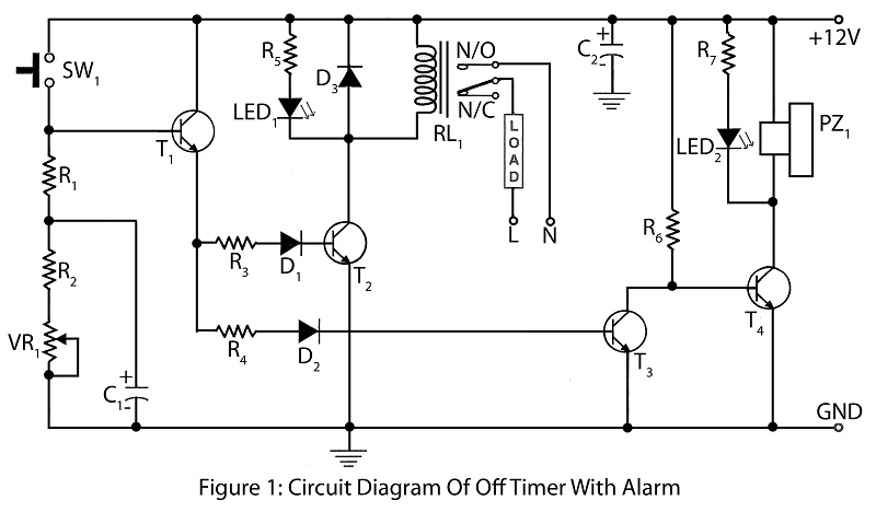
Off timer with alarm with description
An off timer with an alarm is a straightforward project designed to indicate the end of a specified time period. The circuit utilizes four transistors. It includes a circuit diagram along with a parts list and a description of the...
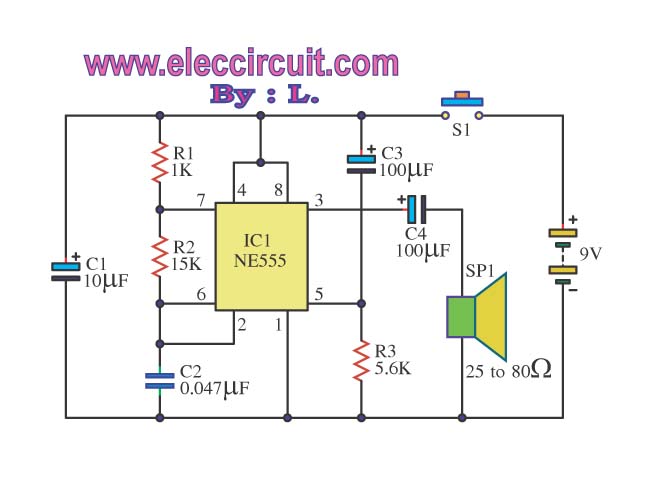
Many simple door buzzer sound circuits
The Door Buzzer circuit utilizes an IC 555 to generate a sound resembling an electric bell. When the switch S1 is pressed, a loud sound is produced. This circuit is designed to be simple and requires minimal components. It is...
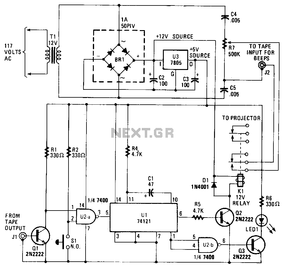
Slide-timer
This circuit records commentary and music on one track of a tape while placing beeps that signal slide changes on another track. The gate U2a triggers U1, which is configured as a timer that generates a pulse each time it...
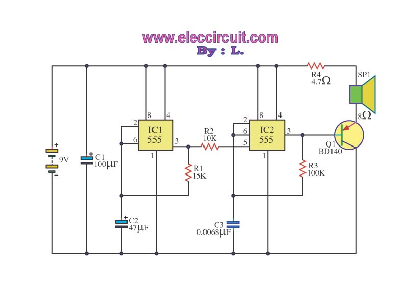
Two sirens sound with ic 555
The operation of the circuit is divided into three parts: low frequency production, high frequency manufacturing, and low frequency extension.
The described circuit functions by segmenting its operation into three distinct sections, each serving a specific purpose in the overall system....
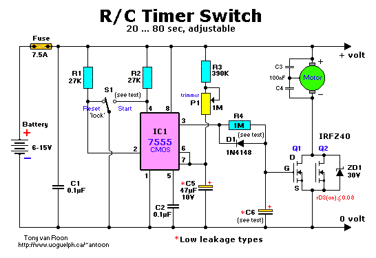
R/C Timer-Switch for Radio Control Applications
The project originated from a request by Tony Bowler, a member of the Long Eaton Club, who sought assistance in converting a "Golden Oldie" model to electric free-flight. He selected Vic Smeed's "Debutante" to be powered by seven AE size...