


AFSK Modem
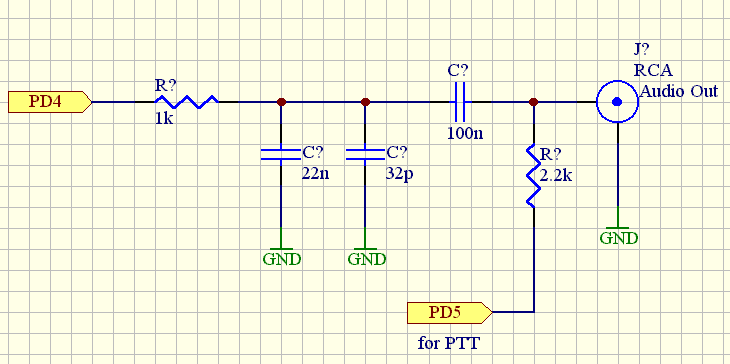
Description: The modulator and demodulator design utilizes an AVR MCU-based program-controlled AFSK modulator due to temperature stability issues with the XR2206 and XR2211 integrated circuits. The modem's size is primarily dictated by the two RCA and DSUB-9 connectors, and while potentiometers could have been used for tuning, a smaller design was prioritized. The modem functions well when tested without a radio, and it establishes stable connections with radios such as the YEASU FT-xxxx series. This modem is particularly effective for remote control applications, including data collection and robotic control. The design incorporates a quartz-controlled modem operating at 950 Hz, 1200 Hz, and 1500 Hz frequencies, with the 950 Hz serving as a guard signal. The digital signal generation employs Direct Digital Synthesis (DDS), and the modem features a standard RS232 connector with settings of 1200 bps, 8 data bits, no parity, and 1 stop bit. Both the transmitter and receiver utilize an AT90S2313 MCU with a 4 MHz clock, with low-pass filters implemented at both ends to smooth the signal.
The circuit design of the modem integrates several key components to ensure reliable operation across various applications. The AVR microcontroller acts as the core processing unit, managing the modulation and demodulation processes. The AFSK modulation technique is employed to encode digital data onto an analog signal, allowing for effective transmission over radio frequencies.
The design employs a Direct Digital Synthesis (DDS) method to generate the required frequencies. By utilizing a series of 32 discrete samples to construct sine waves, the system achieves precise frequency generation. For instance, to create a 1200 Hz signal, the AVR MCU outputs samples at a frequency of 38400 Hz, which corresponds to the necessary sampling rate for accurate signal representation. This process is facilitated by an R-2R ladder network functioning as a Digital-to-Analog Converter (DAC), followed by an RC low-pass filter to smooth out the output waveform.
The temperature stability issue encountered with the original XR2206 and XR2211 ICs prompted the shift to a more robust design. The new quartz-controlled modem operates independently of temperature fluctuations, ensuring consistent performance from -10°C to +50°C. The choice of frequencies—950 Hz, 1200 Hz, and 1500 Hz—was strategic; the close spacing simplifies demodulation and minimizes bandwidth usage, which is crucial when operating with radio transmission.
The modulation scheme assigns specific frequencies to represent binary data: the 1200 Hz frequency signifies a binary '1', while the 1500 Hz frequency represents a binary '0'. The 950 Hz guard signal is continuously monitored by the receiver to maintain connection integrity. This design not only enhances the modem's reliability but also broadens its applicability in various remote control and data acquisition scenarios.
The modem is equipped with a standard RS232 interface, allowing for easy integration with other devices. The communication settings of 1200 bps, 8 data bits, no parity, and 1 stop bit ensure compatibility with a wide range of serial communication protocols. The use of low-pass filters on both the transmitter and receiver sides further enhances signal quality by reducing high-frequency noise, thereby improving overall data integrity during transmission.
In summary, this modem design represents a significant advancement over traditional methods, providing a compact, temperature-stable solution for remote communication applications. Its innovative use of digital synthesis and robust microcontroller architecture ensures reliable performance across various operating conditions.The modulator and the demodulator (pdf < 10 kb). For the easier tuning of the modem it could have been built with potentiometers, but it was easier to reach a smaller size this way (I didn`t want to use SMD potentiometers). Unfortunately, even like this, the size is still too big, because I couldn`t get SMD boxed ICs . Basically the size is determined by the two RCA and the DSUB-9 connectors. At testing, connecting the modem`s input and output without a radio, the modem works perfectly. With YEASU FT-xxxx and similar radios a good and stable connection can be achieved. It is especially good for remotely controlling devices with a simple radio. It is also useful for remote measurement data collection, remote control of models and robots. Unfortunately the original design with the XR2206 and XR2211 pair didn`t work because the temperature dependence of both IC are too big. They work just fine at room temperature, but they become unstable at temperatures of -10. +50 C. For the solution of the transmitter side problems a program-controlled AFSK modulator, running on AVR MCU, was built.
It`s operation is very simple. The sin wave is assembled from 11. 25 degree (32 steps) peaces as the function of the FSK input. Thus, for example, for the generation of a 1200 Hz wave from 32 samples, the samples need to be delivered to one of the 8 bit ports of the AVR with 38400 Hz (2200 Hz *32 = 70400 Hz) frequency. To this port a simple R-2R (8 bites) D/A is connected with an RC low-pass filter at the end. Learning from the trials above, an entirely quartz controlled modem was built. Even though it is a non-standard modem, it still has a wide range of applications, and it is completely temperature independent.
It uses three frequencies 950 Hz, 1200 Hz, 1500 Hz. Selecting frequencies that are so close to each other made the programming of the demodulator much easier, and we saved a little bit on bandwidth (it is important because of the use of radios for the transmission). The 950 Hz is the so called Guard signal. When there is no transmission the receiver uses this frequency to check the existence of the connection with the transmitter.
The 1 and 0 bits are delivered by the 1200 Hz and 1500 Hz frequencies respectively. All frequencies are created digitally (DDS). The modem has a standard RS232 connector, the settings are: 1200 bps, 8, N, 1. In the heart of both the receiver and the transmitter there is a AT90S2313 MCU with 4 MHz clock. The transmitter generates a rectangular signal which goes through an RC low-pass filter before going into the radio`s input. On the receiver`s side there is an RC low-pass filter also. The signal goes through this first before getting into the 2313 comparator, from this the MCU re-assembles the data by measuring period times.
Because of the limited frequency transmission capabilities of the radio, it transmits sin wave signals.
The circuit design of the modem integrates several key components to ensure reliable operation across various applications. The AVR microcontroller acts as the core processing unit, managing the modulation and demodulation processes. The AFSK modulation technique is employed to encode digital data onto an analog signal, allowing for effective transmission over radio frequencies.
The design employs a Direct Digital Synthesis (DDS) method to generate the required frequencies. By utilizing a series of 32 discrete samples to construct sine waves, the system achieves precise frequency generation. For instance, to create a 1200 Hz signal, the AVR MCU outputs samples at a frequency of 38400 Hz, which corresponds to the necessary sampling rate for accurate signal representation. This process is facilitated by an R-2R ladder network functioning as a Digital-to-Analog Converter (DAC), followed by an RC low-pass filter to smooth out the output waveform.
The temperature stability issue encountered with the original XR2206 and XR2211 ICs prompted the shift to a more robust design. The new quartz-controlled modem operates independently of temperature fluctuations, ensuring consistent performance from -10°C to +50°C. The choice of frequencies—950 Hz, 1200 Hz, and 1500 Hz—was strategic; the close spacing simplifies demodulation and minimizes bandwidth usage, which is crucial when operating with radio transmission.
The modulation scheme assigns specific frequencies to represent binary data: the 1200 Hz frequency signifies a binary '1', while the 1500 Hz frequency represents a binary '0'. The 950 Hz guard signal is continuously monitored by the receiver to maintain connection integrity. This design not only enhances the modem's reliability but also broadens its applicability in various remote control and data acquisition scenarios.
The modem is equipped with a standard RS232 interface, allowing for easy integration with other devices. The communication settings of 1200 bps, 8 data bits, no parity, and 1 stop bit ensure compatibility with a wide range of serial communication protocols. The use of low-pass filters on both the transmitter and receiver sides further enhances signal quality by reducing high-frequency noise, thereby improving overall data integrity during transmission.
In summary, this modem design represents a significant advancement over traditional methods, providing a compact, temperature-stable solution for remote communication applications. Its innovative use of digital synthesis and robust microcontroller architecture ensures reliable performance across various operating conditions.The modulator and the demodulator (pdf < 10 kb). For the easier tuning of the modem it could have been built with potentiometers, but it was easier to reach a smaller size this way (I didn`t want to use SMD potentiometers). Unfortunately, even like this, the size is still too big, because I couldn`t get SMD boxed ICs . Basically the size is determined by the two RCA and the DSUB-9 connectors. At testing, connecting the modem`s input and output without a radio, the modem works perfectly. With YEASU FT-xxxx and similar radios a good and stable connection can be achieved. It is especially good for remotely controlling devices with a simple radio. It is also useful for remote measurement data collection, remote control of models and robots. Unfortunately the original design with the XR2206 and XR2211 pair didn`t work because the temperature dependence of both IC are too big. They work just fine at room temperature, but they become unstable at temperatures of -10. +50 C. For the solution of the transmitter side problems a program-controlled AFSK modulator, running on AVR MCU, was built.
It`s operation is very simple. The sin wave is assembled from 11. 25 degree (32 steps) peaces as the function of the FSK input. Thus, for example, for the generation of a 1200 Hz wave from 32 samples, the samples need to be delivered to one of the 8 bit ports of the AVR with 38400 Hz (2200 Hz *32 = 70400 Hz) frequency. To this port a simple R-2R (8 bites) D/A is connected with an RC low-pass filter at the end. Learning from the trials above, an entirely quartz controlled modem was built. Even though it is a non-standard modem, it still has a wide range of applications, and it is completely temperature independent.
It uses three frequencies 950 Hz, 1200 Hz, 1500 Hz. Selecting frequencies that are so close to each other made the programming of the demodulator much easier, and we saved a little bit on bandwidth (it is important because of the use of radios for the transmission). The 950 Hz is the so called Guard signal. When there is no transmission the receiver uses this frequency to check the existence of the connection with the transmitter.
The 1 and 0 bits are delivered by the 1200 Hz and 1500 Hz frequencies respectively. All frequencies are created digitally (DDS). The modem has a standard RS232 connector, the settings are: 1200 bps, 8, N, 1. In the heart of both the receiver and the transmitter there is a AT90S2313 MCU with 4 MHz clock. The transmitter generates a rectangular signal which goes through an RC low-pass filter before going into the radio`s input. On the receiver`s side there is an RC low-pass filter also. The signal goes through this first before getting into the 2313 comparator, from this the MCU re-assembles the data by measuring period times.
Because of the limited frequency transmission capabilities of the radio, it transmits sin wave signals.
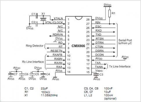
CMX866 V.22 Bis Modem With AT Commands
The CMX867A is a multi-standard modem designed for telephone-based information and telemetry systems. Control of the device is managed through a high-speed serial bus that is compatible with various types of C serial interfaces. The data transmitted and received by...
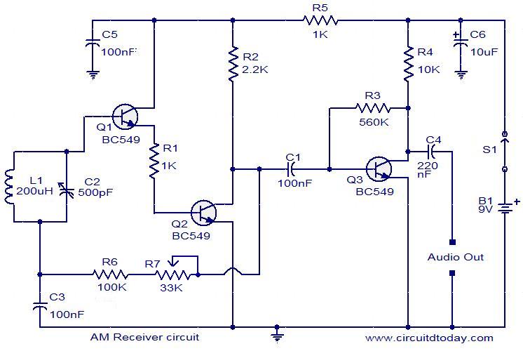
Circuit diagram of a modulator circuit in a transmitter and receiver of a amplitude modulation
Circuit diagram of a modulator circuit in a transmitter and receiver of amplitude modulation.
The modulator circuit in an amplitude modulation (AM) transmitter and receiver plays a crucial role in the process of encoding information onto a carrier wave. In a...
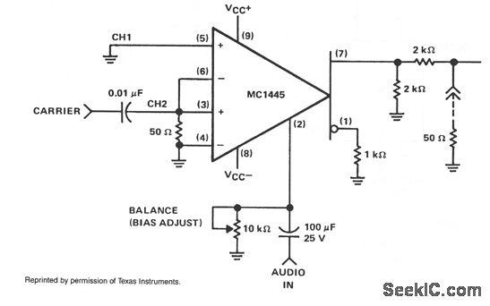
BALANCED MODULATOR
When the carrier level is sufficient to activate the cross-coupled pair of differential amplifiers, the modulation signal applied to the gate will switch at the carrier frequency between the collector loads. This switching process results in the modulation being multiplied...
tune coil
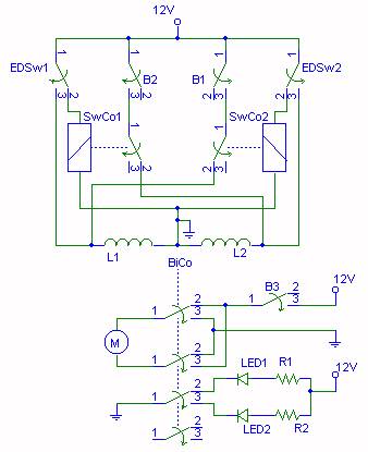
Tuning a system is typically a challenging task. The user must power the system, observe the spark length, shut it down, adjust the primary tap, restart, and repeat this process until the spark length is optimized. However, using a tuning...
BALANCED MODULATOR DEMODULATOR
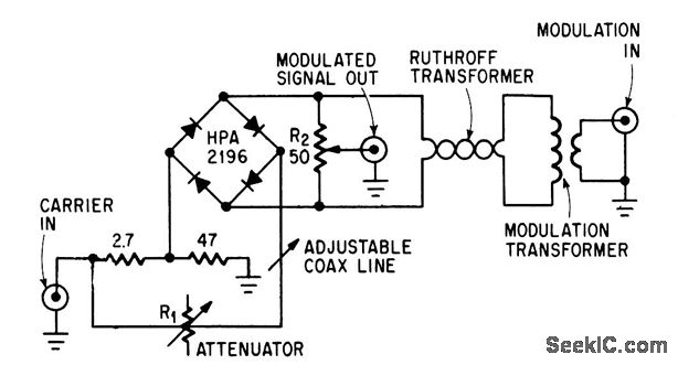
This circuit achieves high carrier and modulation suppression by utilizing closely matched diodes. It includes resistor R1 for amplitude adjustment and a coaxial line for phase adjustment. Resistor R2 allows for slight amplitude adjustments.
The described circuit is a diode...
UPDATED ST-5 MAINLINE DEMODULATOR
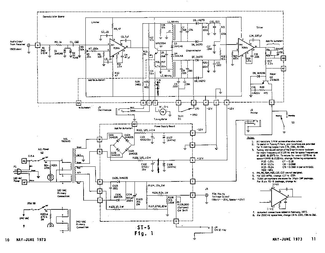
The Mainline ST-5 was introduced in the RTTY Journal in May 1970 and has quickly become a popular demodulator for RTTY. Due to the unavailability of back issues, the original article is being reprinted. Those interested in 100 baud speed...

Modem/Fax Protector For Two Computers Circuit
This modem/fax protector can be utilized in telephone-line connections between a PC or a terminal and a remote computer. In this circuit, the surge voltage protectors (SVPs) are rated at 230 V. Additionally, a proper grounding is essential for optimal...

SMD project
This is my first project with an SMD circuit. I previously avoided SMD components due to confusion caused by their small size. The circuit for the current SMD project involves headphones.
The project focuses on designing a compact headphone amplifier using...
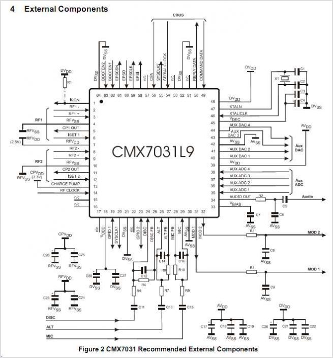
CMX7031Q1 The Two-Way Radio Processor
The CMX866 is a multi-standard modem designed for use in telephone-based information and telemetry systems. Control of the device is achieved through AT commands via a simple 9600 b/s serial interface, which is compatible with various types of host controllers....