


Bus Description RS423 Serial Interface
#RS423
#serial interface
#EIA/TIA-423
#unbalanced voltage
#digital interface
#driver
#receiver
#telecommunication
#data transmission
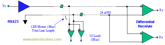
Description: The EIA/TIA-423 Unbalanced (Single-Ended) interface specifies a single, unidirectional driver with multiple receivers (up to 10). It outlines the electrical characteristics of the unbalanced voltage digital interface circuit, typically implemented in integrated circuit technology, which can be used for the interchange of serial binary signals between Data Terminal Equipment (DTE) and Data Circuit-Terminating Equipment (DCE), or in any point-to-point interconnection of serial binary signals between digital devices. The Telecommunications Industry Association's EIA/TIA-449 defines a general-purpose 37-position interface for DTE and DCE employing serial binary data interchange. This standard serves as a mechanical interface for the transmission of balanced and unbalanced signals among various higher-end computers, media, and multimedia peripherals. EIA/TIA-530, which is a high-speed 25-position interface for DTE and DCE, including an alternative 26-position connector, serves as a replacement for EIA-449, utilizing a DB-25 (EIA-232-D) connector instead of a 37-pin connector while maintaining the essential electrical signals. Typically, EIA-422 and RS-423 systems are not compatible. EIA-449 cabling for EIA-422 sends and receives data as differential pairs and control signals as single-ended, whereas EIA-423 cabling transmits and receives single-ended data and control signals. Receiving a single-ended signal in EIA-423 is achieved by grounding the 'B' side of the differential receiver at the connector. If the system adheres to the EIA-449 cabling specification, then one 'B' side of the differential receiver on the EIA-423 side will be grounded at the connector, prompting the differential driver on the EIA-422 side to drive ground. The EIA-422 side also employs a termination resistor between the ends of its differential receiver, creating a 120-ohm short to ground for the EIA-423 driver. If systems were connected without regard for RS-499, the system would revert to EIA-423 (single-ended) distance and data rate, primarily due to the single-ended driver on the RS-423 side, while the receiver on the RS-422 side would accept the single-ended EIA-423 signal and ground on its differential pair.
The EIA/TIA-423 interface is a critical standard in the realm of telecommunications, particularly for applications requiring the reliable transmission of serial binary data. The architecture of this interface supports a unidirectional communication model, where a single driver can support multiple receivers, making it efficient for certain types of network configurations. This characteristic is particularly beneficial in scenarios where multiple devices need to receive the same data stream, such as in broadcasting applications or multi-device control systems.
In practical applications, the EIA-423 interface is often implemented in integrated circuits designed specifically for digital communication. These circuits are engineered to handle the electrical characteristics defined in the standard, ensuring compatibility and reliability across various devices. The integration of this interface into digital devices allows for seamless communication between DTE and DCE, facilitating data exchange in environments such as computer networking and industrial automation.
The EIA/TIA-449 and EIA/TIA-530 interfaces further enhance the capabilities of the EIA-423 standard by providing mechanical and electrical compatibility with a broader range of devices. The transition from a 37-pin to a 25-pin connector in EIA-530 simplifies connections while preserving essential signal integrity. This adaptability is crucial in modern systems where space and efficiency are paramount.
Understanding the differences between EIA-422 and EIA-423 is vital for engineers working with these standards. The differential signaling in EIA-422 offers advantages in noise immunity and signal integrity over longer distances, while the single-ended approach of EIA-423 simplifies the design and implementation of certain applications. However, care must be taken when interfacing these two standards, as improper connections can lead to signal degradation or system failure.
Overall, the EIA/TIA-423 standard plays a significant role in the design and implementation of digital communication systems, providing a framework for reliable data transmission in various applications. Its specifications ensure that engineers can develop systems that meet the demands of modern telecommunications while maintaining compatibility with existing technologies.The EIA/TIA-423 Unbalanced (Single-Ended) interface; specifies a single, unidirectional driver with multiple receivers (up to 10). ". Specifies the electrical characteristics of the unbalanced voltage digital interface circuit, normally implemented in integrated circuit technology, that may be employed when specified for the interchange of serial b
inary signals between Data Terminal Equipment (DTE) and Data Circuit-Terminating Equipment (DCE) or in any point-to-point interconnection of serial binary signals between digital equipment. " `Telecommunications Industry Association` EIA/TIA-449 ; General Purpose 37-Position Interface fro Data terminal Equipment and Data Circuit-Terminating Equipment Employing Serial binary Data Interchange A serial mechanical interface standard for transmission of balanced and unbalanced signals between a variety of higher-end computer, media, and multimedia peripherals.
EIA/TIA-530 ; High Speed 25-Position Interface for Data Terminal Equipment and Data Circuit-Terminating Equipment, Including Alternative 26-Position Connector EIA530 is a replacement for EIA-449 that uses a DB-25 ( EIA-232-D ) connector instead of a 37-pin connector, while keeping the most important electrical signals intact. Normally EIA422 and RS-423 systems may not be connected together. EIA-449 cabling of 422 sends and receives data as differential pairs and control signal as single-ended, but for 423 cabling it sends and receives single-ended data and control signals.
Receiving the single ended signal in 423 is accomplished by grounding the `B` side of the differential receiver at the connector. So if the system follows the EIA-449 (cabling) specification than one (B) side of the differential receiver of the 423 side will be grounded at the connector forcing the differential driver on the 422 side to drive ground.
The EIA422 side also uses a termination resistor between the ends of its differential receiver, providing a serious 120 ohm short to ground for the 423 driver. If the systems were to be connected together (with out regard for RS499) than the system would revert to EIA423 (single-ended) distance and data rate ~ Only because the driver on the RS423 side is single ended, while the receiver on the RS422 side would receive the single-ended 423 signal and ground on its differential pair.
The EIA/TIA-423 interface is a critical standard in the realm of telecommunications, particularly for applications requiring the reliable transmission of serial binary data. The architecture of this interface supports a unidirectional communication model, where a single driver can support multiple receivers, making it efficient for certain types of network configurations. This characteristic is particularly beneficial in scenarios where multiple devices need to receive the same data stream, such as in broadcasting applications or multi-device control systems.
In practical applications, the EIA-423 interface is often implemented in integrated circuits designed specifically for digital communication. These circuits are engineered to handle the electrical characteristics defined in the standard, ensuring compatibility and reliability across various devices. The integration of this interface into digital devices allows for seamless communication between DTE and DCE, facilitating data exchange in environments such as computer networking and industrial automation.
The EIA/TIA-449 and EIA/TIA-530 interfaces further enhance the capabilities of the EIA-423 standard by providing mechanical and electrical compatibility with a broader range of devices. The transition from a 37-pin to a 25-pin connector in EIA-530 simplifies connections while preserving essential signal integrity. This adaptability is crucial in modern systems where space and efficiency are paramount.
Understanding the differences between EIA-422 and EIA-423 is vital for engineers working with these standards. The differential signaling in EIA-422 offers advantages in noise immunity and signal integrity over longer distances, while the single-ended approach of EIA-423 simplifies the design and implementation of certain applications. However, care must be taken when interfacing these two standards, as improper connections can lead to signal degradation or system failure.
Overall, the EIA/TIA-423 standard plays a significant role in the design and implementation of digital communication systems, providing a framework for reliable data transmission in various applications. Its specifications ensure that engineers can develop systems that meet the demands of modern telecommunications while maintaining compatibility with existing technologies.The EIA/TIA-423 Unbalanced (Single-Ended) interface; specifies a single, unidirectional driver with multiple receivers (up to 10). ". Specifies the electrical characteristics of the unbalanced voltage digital interface circuit, normally implemented in integrated circuit technology, that may be employed when specified for the interchange of serial b
inary signals between Data Terminal Equipment (DTE) and Data Circuit-Terminating Equipment (DCE) or in any point-to-point interconnection of serial binary signals between digital equipment. " `Telecommunications Industry Association` EIA/TIA-449 ; General Purpose 37-Position Interface fro Data terminal Equipment and Data Circuit-Terminating Equipment Employing Serial binary Data Interchange A serial mechanical interface standard for transmission of balanced and unbalanced signals between a variety of higher-end computer, media, and multimedia peripherals.
EIA/TIA-530 ; High Speed 25-Position Interface for Data Terminal Equipment and Data Circuit-Terminating Equipment, Including Alternative 26-Position Connector EIA530 is a replacement for EIA-449 that uses a DB-25 ( EIA-232-D ) connector instead of a 37-pin connector, while keeping the most important electrical signals intact. Normally EIA422 and RS-423 systems may not be connected together. EIA-449 cabling of 422 sends and receives data as differential pairs and control signal as single-ended, but for 423 cabling it sends and receives single-ended data and control signals.
Receiving the single ended signal in 423 is accomplished by grounding the `B` side of the differential receiver at the connector. So if the system follows the EIA-449 (cabling) specification than one (B) side of the differential receiver of the 423 side will be grounded at the connector forcing the differential driver on the 422 side to drive ground.
The EIA422 side also uses a termination resistor between the ends of its differential receiver, providing a serious 120 ohm short to ground for the 423 driver. If the systems were to be connected together (with out regard for RS499) than the system would revert to EIA423 (single-ended) distance and data rate ~ Only because the driver on the RS423 side is single ended, while the receiver on the RS422 side would receive the single-ended 423 signal and ground on its differential pair.
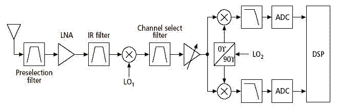
receiver architectures
Various architectures of receivers have been proposed in literature, but the most popular architectures among them, such as Heterodyne, Homodyne, Wideband-IF, and Low-IF, are presented here.
The Heterodyne receiver architecture utilizes two frequencies: the incoming radio frequency (RF) signal and a...
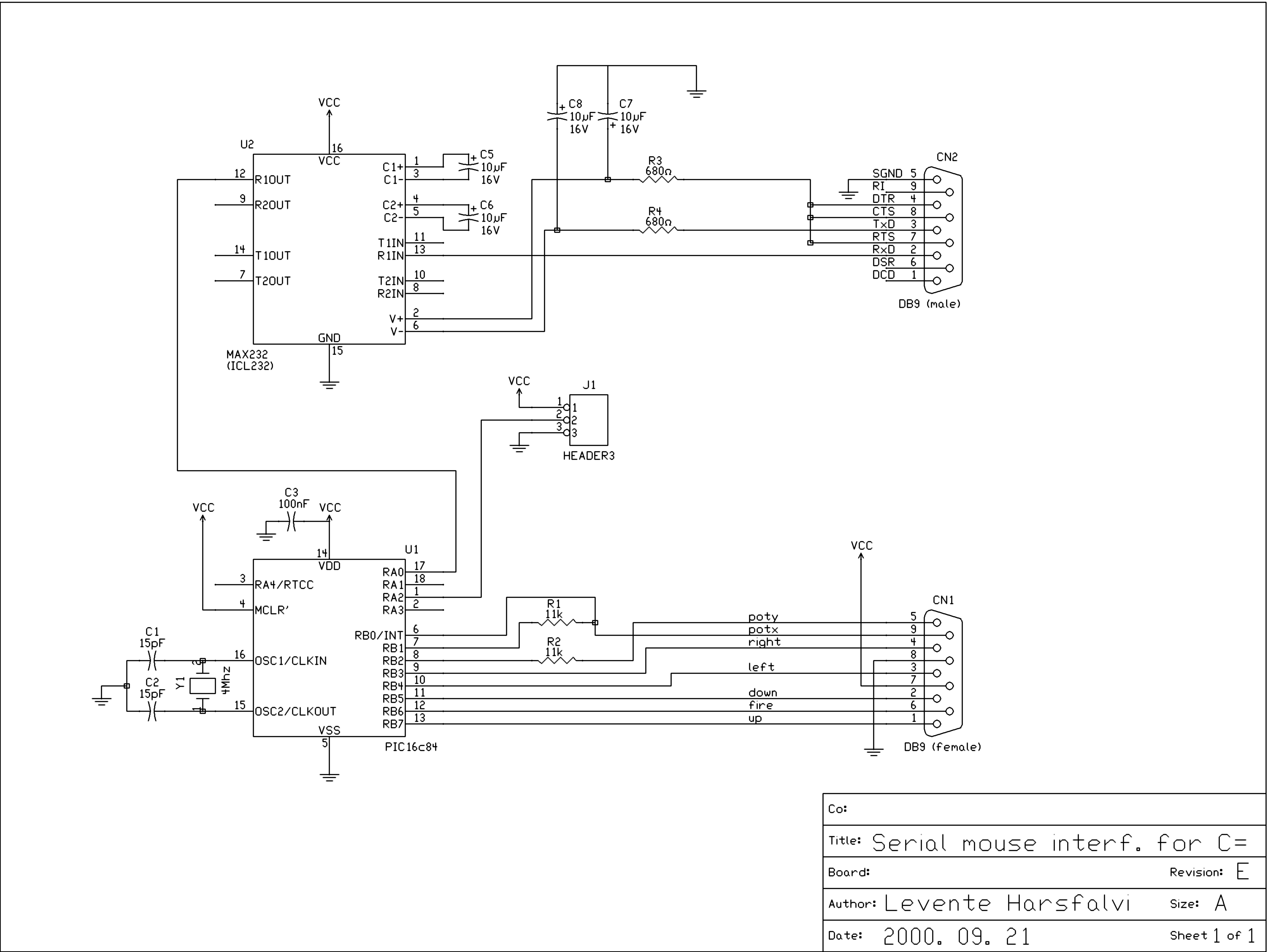
Serial mouse interface for Commodore
This interface design has a long history. It is the first microcontroller design initiated in early 1998, which has evolved over the years. Initially, the schematic diagram for the first prototype was drafted in 1998, and it later became the...
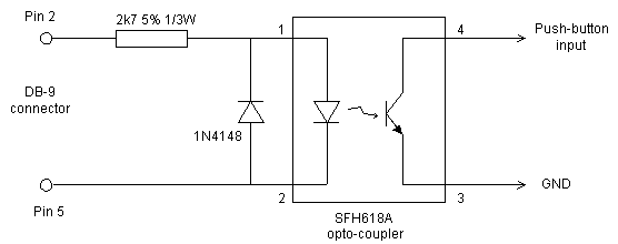
Serial Remote Control for the RIG RX-2 Receiver
This document outlines modifications made to the RIG RX-2 receiver, enabling remote control via a computer using an RS-232 serial interface. The modifications consist of two components: additional hardware and a new firmware program for the PIC16C84 microcontroller. In manual...
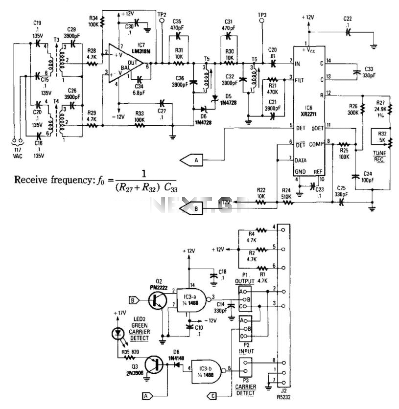
Carrier-Current Receiver For Data Transmission
This receiver consists of an input network, amplifier IC7, FSK PLL detector IC8, and output amplifier/interface circuits Q2, Q3, IC3A, and IC3B, which include a 1488 Quad RS232 line driver for the carrier-current signal. The tuned amplifier IC7 amplifies this...
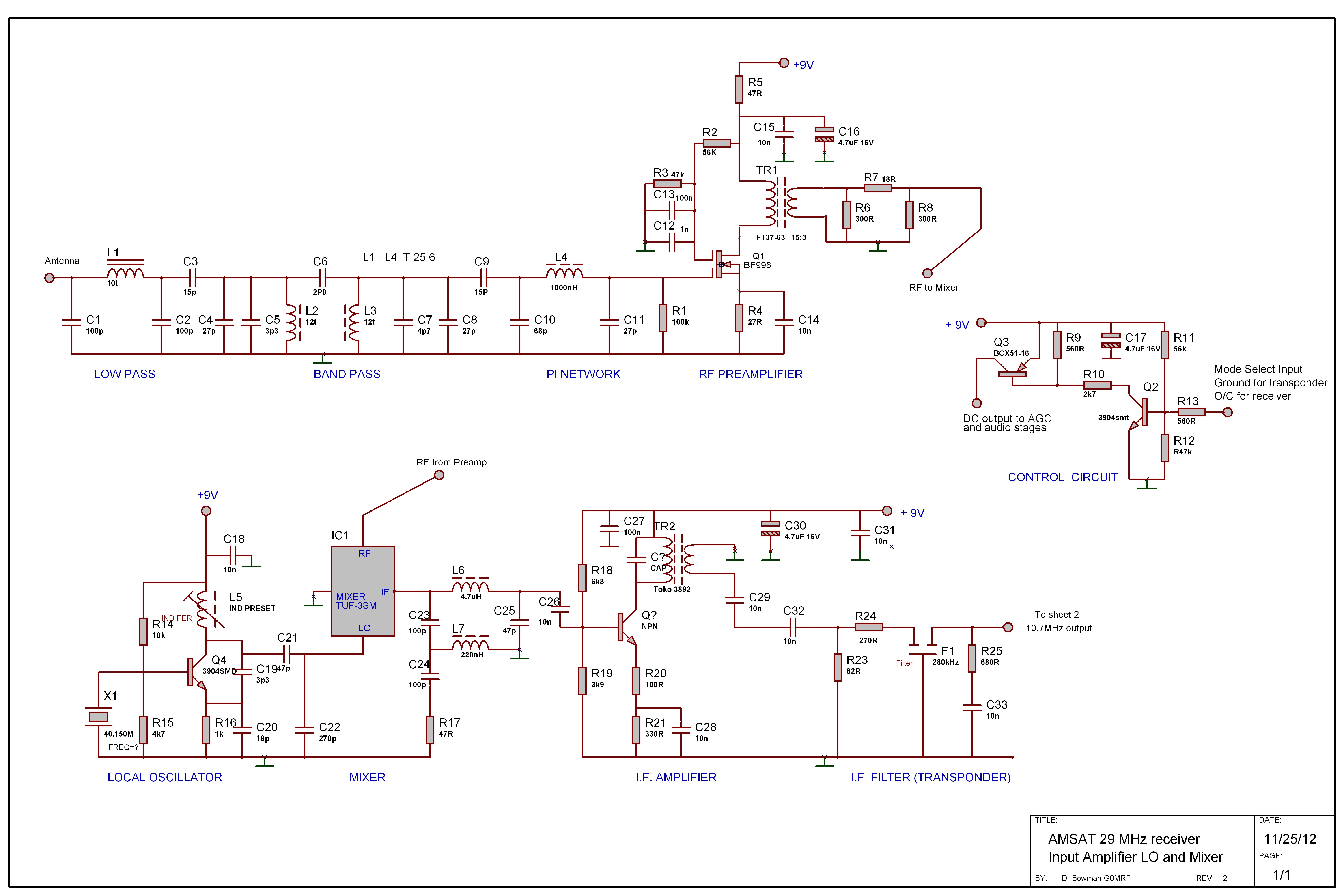
G0MRF 29.45 MHz Receiver Project
In 2007 and 2008, AMSAT-UK dedicated significant effort to a proposal for the European Space Agency (ESA) to include an Amateur Radio payload on the mass dummy during the maiden flight of the VEGA launcher. This initiative was referred to...
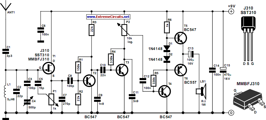
Tuned Radio Frequency (TRF) Receiver
Superheterodyne receivers have been mass-produced since around 1924, but for reasons of cost did not become successful until the 1930s.
Superheterodyne receivers represent a pivotal advancement in radio technology, characterized by their ability to convert high-frequency signals into lower intermediate...
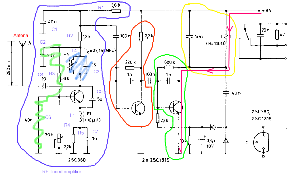
signal Can someone break down how this receiver works
The circuit described is a toy car receiver, which operates similarly to the transmitter but in reverse and with additional filtering. The receiver is tuned to a frequency of 27.145 MHz to capture signals at this frequency. Following the initial...
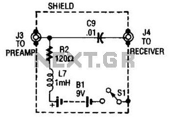
Receiver-Interface Circuit For Preamps Circuit
The purpose of the receiver/interface circuit is to pass RF to the receiver through capacitor C9, while adding DC power to the feedline through resistor R2 and RF choke L7.
The receiver/interface circuit is designed to facilitate the transmission of radio...
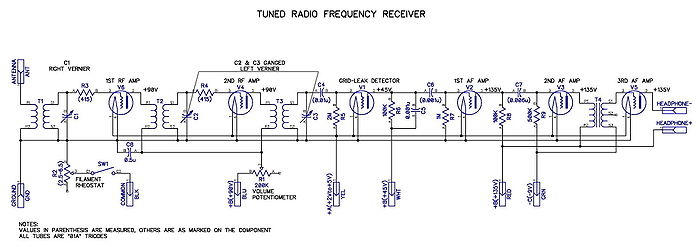
Tuned radio frequency receiver
A tuned radio frequency (TRF) receiver is a radio receiver typically consisting of multiple tuned radio frequency amplifiers followed by circuits for detecting and amplifying the audio signal. A three-stage TRF receiver includes an RF stage, a detector stage, and...