


Electronic Cw Bug Keyer Circuit
#CW bug keyer
#skin conductivity
#inverter
#oscillator
#square wave
#dit paddle
#logic high
#keying
#low-frequency
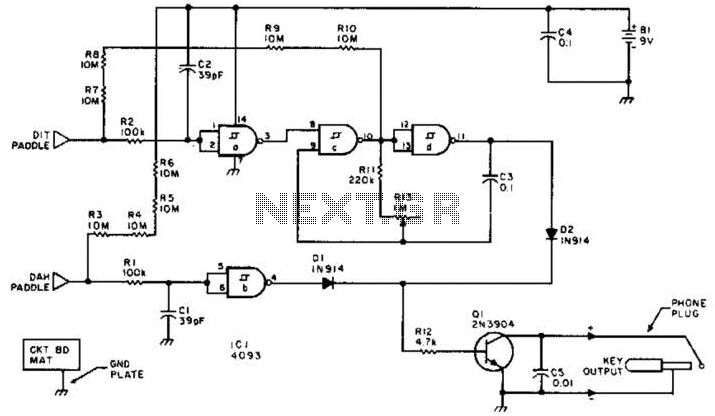
Description: This keyer utilizes skin conductivity to emulate the traditional mechanical CW bug keyer. When the dit paddle is activated, the bias on the inverter, IC1-a, is routed to ground, resulting in a logic high output. This triggers oscillator sections CD to create a low-frequency square wave keying signal Q1 for a succession of dits. Additionally, when the dah paddle is activated, section b generates a logic high, turning on keyer Q1.
The described keyer circuit operates by leveraging the principle of skin conductivity, which allows for a touch-sensitive interface that mimics the functionality of a mechanical keyer. The core component, an inverter labeled IC1-a, plays a pivotal role in detecting the paddle activation. When the dit paddle is touched, it effectively shunts the bias voltage to ground. This action results in a logic high output from the inverter, which serves as a control signal for the subsequent oscillator stages.
The oscillator sections, denoted as CD, are responsible for generating a low-frequency square wave output. This square wave acts as a keying signal, identified as Q1, which corresponds to a series of dits. The frequency of the square wave can be adjusted based on the design parameters of the oscillator circuit, allowing for customization of the dit duration.
In parallel, the dah paddle is connected to section b of the circuit, which functions similarly by producing a logic high when activated. This output directly drives keyer Q1, ensuring that a longer keying duration is established for dahs. The interaction between the two paddles allows for seamless operation, where the user can produce Morse code by simply touching the respective paddles.
Overall, this keyer circuit exemplifies a modern adaptation of traditional telegraphy methods, providing an intuitive and responsive mechanism for generating Morse code signals through simple touch inputs. The design emphasizes reliability and ease of use, making it suitable for amateur radio operators and enthusiasts seeking a tactile keying experience. This keyer uses skin conductivity to simulate the old-fashioned mechanical CW bug keyer. When the dit paddle is touched the bias on the inverter, ICl-a is shunted to ground, and it produces a logic high, causing oscillator sections CD to generate a low-frequency square wave keying Ql for a series of dits. When the dah paddle is touched, section b produces a logic high, driving keyer Ql on.
The described keyer circuit operates by leveraging the principle of skin conductivity, which allows for a touch-sensitive interface that mimics the functionality of a mechanical keyer. The core component, an inverter labeled IC1-a, plays a pivotal role in detecting the paddle activation. When the dit paddle is touched, it effectively shunts the bias voltage to ground. This action results in a logic high output from the inverter, which serves as a control signal for the subsequent oscillator stages.
The oscillator sections, denoted as CD, are responsible for generating a low-frequency square wave output. This square wave acts as a keying signal, identified as Q1, which corresponds to a series of dits. The frequency of the square wave can be adjusted based on the design parameters of the oscillator circuit, allowing for customization of the dit duration.
In parallel, the dah paddle is connected to section b of the circuit, which functions similarly by producing a logic high when activated. This output directly drives keyer Q1, ensuring that a longer keying duration is established for dahs. The interaction between the two paddles allows for seamless operation, where the user can produce Morse code by simply touching the respective paddles.
Overall, this keyer circuit exemplifies a modern adaptation of traditional telegraphy methods, providing an intuitive and responsive mechanism for generating Morse code signals through simple touch inputs. The design emphasizes reliability and ease of use, making it suitable for amateur radio operators and enthusiasts seeking a tactile keying experience. This keyer uses skin conductivity to simulate the old-fashioned mechanical CW bug keyer. When the dit paddle is touched the bias on the inverter, ICl-a is shunted to ground, and it produces a logic high, causing oscillator sections CD to generate a low-frequency square wave keying Ql for a series of dits. When the dah paddle is touched, section b produces a logic high, driving keyer Ql on.
The Ecology of the Oscillator Transmitter
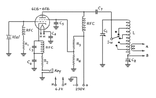
An oscillator-only transmitter appears to be the simplest way to access the radio airwaves; however, it presents several challenges as part of a transmitting and receiving station. The issue of finding an adequate crystal-controlled transmitter for newcomers wishing to operate...
Low-frequency-converter
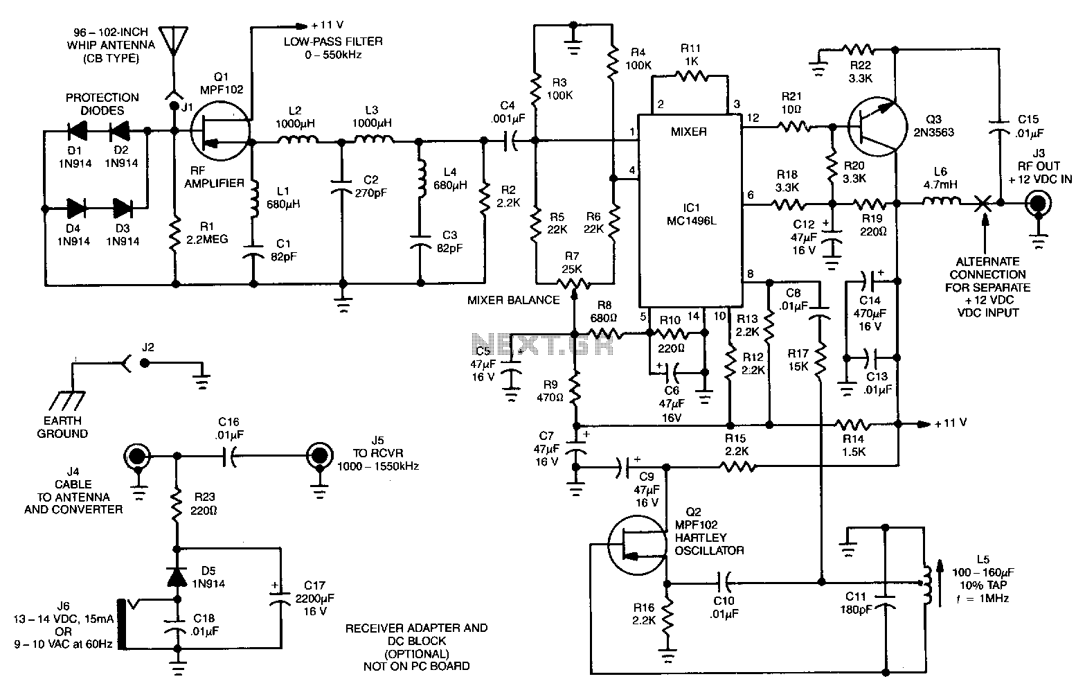
The signals below 550 kHz include maritime mobile, distress signals, radio beacons, aircraft weather information, European Longwave-AM broadcasts, and point-to-point communications. A low-frequency converter transforms the 10 to 500 kHz LW range into a 1010 to 1550 kHz MW range...
coil coupled operation metal
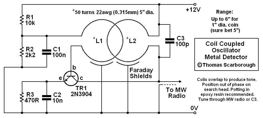
The metal detector presented may represent a new category in its field. After some exposure, it has been recognized as such by those familiar with it. This device is based on a standard transformer coupled oscillator (TCO), which is why...
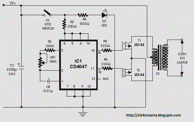
100w inverter circuit by irf44 mosfet
It is recommended to have a fuse in the power line and to always have a load connected while power is being applied. The fuse should be rated at 10 amps per 100 watts of output. The power leads must...
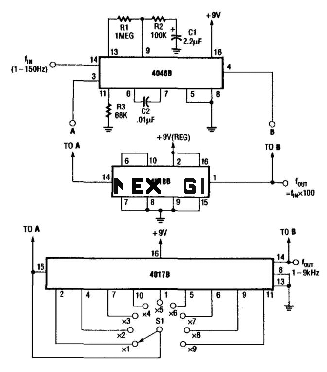
Low-Frequency Prescaler
For multiplying frequencies in the 1 to 150 Hz range, this circuit utilizes a 4046B phase-locked loop (PLL) and a 100 prescaler. The output from the voltage-controlled oscillator (VCO) is phase-locked to the low-frequency input. This configuration facilitates the use...
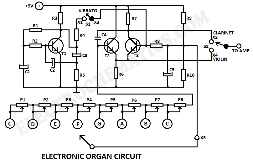
Electronic Organ Circuit
This electronic organ circuit is straightforward to construct and primarily consists of an emitter-coupled oscillator formed by transistors T2 and T3. A square wave voltage can be obtained from the collector of T3 (X2), which imparts a clarinet-like quality to...
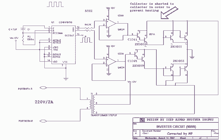
500W 12V to 220V inverter
Using this circuit you can convert the 12V dc into the 220V Ac. In this circuit, 4047 is used to generate the square wave of 50Hz and amplify the current and then amplify the voltage by using the step transformer....
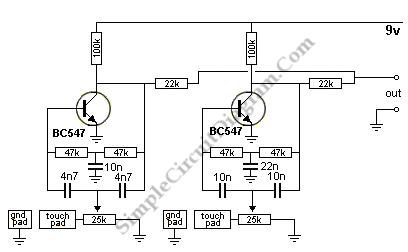
Electronic Drum Synthesizer
The circuit consists of two twin-T oscillators set below the oscillation threshold. To initiate oscillation, a touch on the Touch Pad is required. The schematic diagram illustrates the circuit, where different touch patterns on the pads can create a variety...
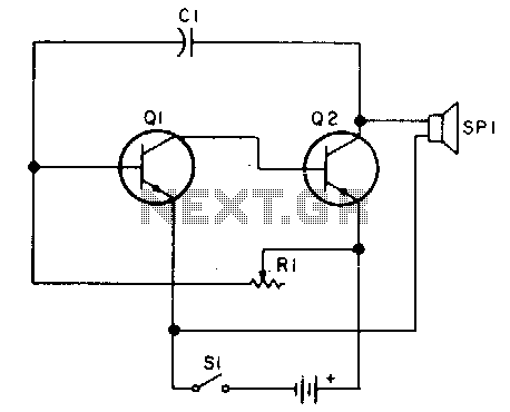
Code practice oscillator II
Oscillator, operates with 2 to 12 volts DC (optimal performance is achieved at 9 to 12 volts for maximum volume and clear keying). Additionally, R1 can be substituted with a 500K potentiometer, allowing the circuit to sweep across the entire...