


Interface circuit fsk modulation and power lines
#FSK modulation
#power lines
#serial coded signal
#high voltage isolation
#556 timer
#astable multivibrator
#signal amplification
#control signal
#transmission
#modulation
Description: The circuit features a serial coded modulated control signal that amplifies and transmits high-voltage isolation. It utilizes a 556 timer-based circuit along with resistors R1, R2, capacitors C1, and R3, R4, C2 to form two astable multivibrators. The circuit generates two signals at frequencies of 100 kHz and 90 kHz. A serial control signal is directed to the analog switch CC4066. The output of the resonant harmonic at 100 kHz is amplified by amplifier VT1 and is isolated and coupled to the power line via transformers T, CX1, and CX2. Transformer T1 and capacitor C8 form a frequency selection circuit, while T, CX1, and CX2 create a high-voltage isolation circuit. When the serial signal is low, the 556 timer outputs a harmonic at 90 kHz to amplifier VT2, which is also resonantly amplified and isolated before being coupled to the power line. This circuit is designed to utilize the power line carrier channel for the transmission of control signals.
The circuit operates by generating two distinct frequencies for the modulation of control signals. The 556 timer IC is configured in an astable mode, which allows it to oscillate continuously, producing square waves at the designated frequencies of 100 kHz and 90 kHz. The resistors and capacitors are carefully selected to determine the frequency of oscillation, ensuring that the output signals are stable and within the desired frequency range.
The analog switch CC4066 is employed to control the flow of the serial coded modulated signal, allowing for dynamic control over the transmission process. This capability is essential for applications that require precise signal management.
The amplifiers VT1 and VT2 serve to boost the power of the generated signals, making them suitable for transmission over the power line. The use of transformers T, CX1, and CX2 provides necessary high-voltage isolation, ensuring that the control signals do not interfere with the main power line and are safely transmitted without risk of electrical shock or damage to other components.
The frequency selection circuit formed by T1 and C8 plays a crucial role in filtering and selecting the appropriate frequencies for transmission, optimizing the circuit's performance in various operational conditions. This setup allows the circuit to effectively utilize power line communication techniques, making it suitable for remote control applications and other scenarios where signal transmission over existing power infrastructure is required.
Overall, the design emphasizes reliability and efficiency, ensuring that control signals can be transmitted effectively while maintaining high-voltage safety standards. Circuit serial coded modulated control signal, amplify, and transmit high voltage isolation. 556 time base circuit and R1, R2, C1 and R3, R4, C2 form two astable multivibrator, 100kHz and 90kHz to generate two signals. Serial control signal to the analog switch CC4066 control. 5 556 feet high when the output of the resonant harmonic 100kHz to VT1 amplifier and T, CX1, CX2 isolation, coupled to the power line. T1, C8 composition selected frequency circuits, T, CX1, CX2 composed of high-voltage isolation circuit.
The serial signal is low, 556 feet 9 output harmonic 90kHz to VT2, by resonance amplification and T, CX1, CX2 isolation coupled to the power line. This circuit can use power line carrier channel to transmit control signals.
The circuit operates by generating two distinct frequencies for the modulation of control signals. The 556 timer IC is configured in an astable mode, which allows it to oscillate continuously, producing square waves at the designated frequencies of 100 kHz and 90 kHz. The resistors and capacitors are carefully selected to determine the frequency of oscillation, ensuring that the output signals are stable and within the desired frequency range.
The analog switch CC4066 is employed to control the flow of the serial coded modulated signal, allowing for dynamic control over the transmission process. This capability is essential for applications that require precise signal management.
The amplifiers VT1 and VT2 serve to boost the power of the generated signals, making them suitable for transmission over the power line. The use of transformers T, CX1, and CX2 provides necessary high-voltage isolation, ensuring that the control signals do not interfere with the main power line and are safely transmitted without risk of electrical shock or damage to other components.
The frequency selection circuit formed by T1 and C8 plays a crucial role in filtering and selecting the appropriate frequencies for transmission, optimizing the circuit's performance in various operational conditions. This setup allows the circuit to effectively utilize power line communication techniques, making it suitable for remote control applications and other scenarios where signal transmission over existing power infrastructure is required.
Overall, the design emphasizes reliability and efficiency, ensuring that control signals can be transmitted effectively while maintaining high-voltage safety standards. Circuit serial coded modulated control signal, amplify, and transmit high voltage isolation. 556 time base circuit and R1, R2, C1 and R3, R4, C2 form two astable multivibrator, 100kHz and 90kHz to generate two signals. Serial control signal to the analog switch CC4066 control. 5 556 feet high when the output of the resonant harmonic 100kHz to VT1 amplifier and T, CX1, CX2 isolation, coupled to the power line. T1, C8 composition selected frequency circuits, T, CX1, CX2 composed of high-voltage isolation circuit.
The serial signal is low, 556 feet 9 output harmonic 90kHz to VT2, by resonance amplification and T, CX1, CX2 isolation coupled to the power line. This circuit can use power line carrier channel to transmit control signals.
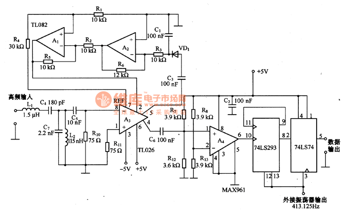
The FSK modulation circuit composed of 74LS74
This is an FSK modulation circuit composed of the 74LS74. The FSK modulation circuit does not include a phase-locked loop (PLL) or a high-Q bandpass filter, eliminating the need for tuning adjustments in the high-frequency modulation circuit. The two tuning...
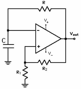
Design of astable multivibrator
An astable multivibrator needs to be designed, and the maximum and minimum frequencies generated at the output must be calculated.
An astable multivibrator is a type of oscillator circuit that continuously switches between its high and low states without requiring any...
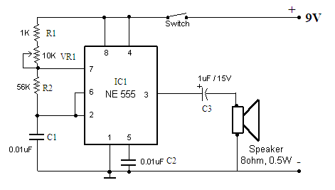
Astable Multivibrator Electronic
Function: to trigger a device or operate in free-running mode. Components: Battery, Charger, Battery Connector, Capacitor, Integrated Circuit (IC), Resistor VR1-10K, Resistor R1-1K, Resistor R2.
The described circuit functions either to trigger a connected device or to operate in a free-running...
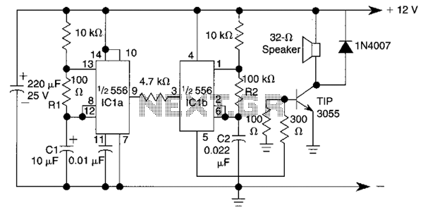
Warble Alarm Circuit
This circuit utilizes a 556 timer IC to initially generate a low-frequency square wave, which is then modulated to produce two alternating tones of approximately 400 Hz and 500 Hz. The circuit is designed to create a warble alarm similar...
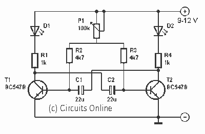
Astable multivibrator with two LED
This is one of the basic circuitry of the electronics. The multivibrator astable shows two LEDs alternately light up with an adjustable speed. The circuit uses two transistors conduct alternately by the capacitors charged and discharged. The rate at which...

556 controls temperature and liquid level
One-half of a 556 dual timer monitors the temperature of a liquid bath, controlling a heating element that maintains temperature within ±2°C over a 32° - 200°C range. The other half monitors the liquid level, disconnecting the heater when the...
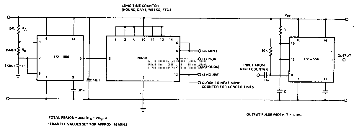
Long time delay
In the 556 timer, the timing is determined by the charging rate of the external capacitor. For prolonged time delays, capacitors with extremely low leakage are necessary, which can be costly. The practicality of the components involved restricts the time...
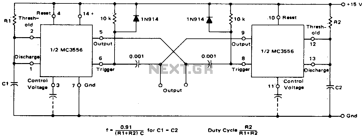
Dual astable multivibrator
This dual astable multivibrator offers versatility not found in single timer circuits. The duty cycle can be adjusted from 5% to 95%. The two outputs generate two-phase clock signals, which are frequently required in digital systems. Additionally, it can be...
Transmission
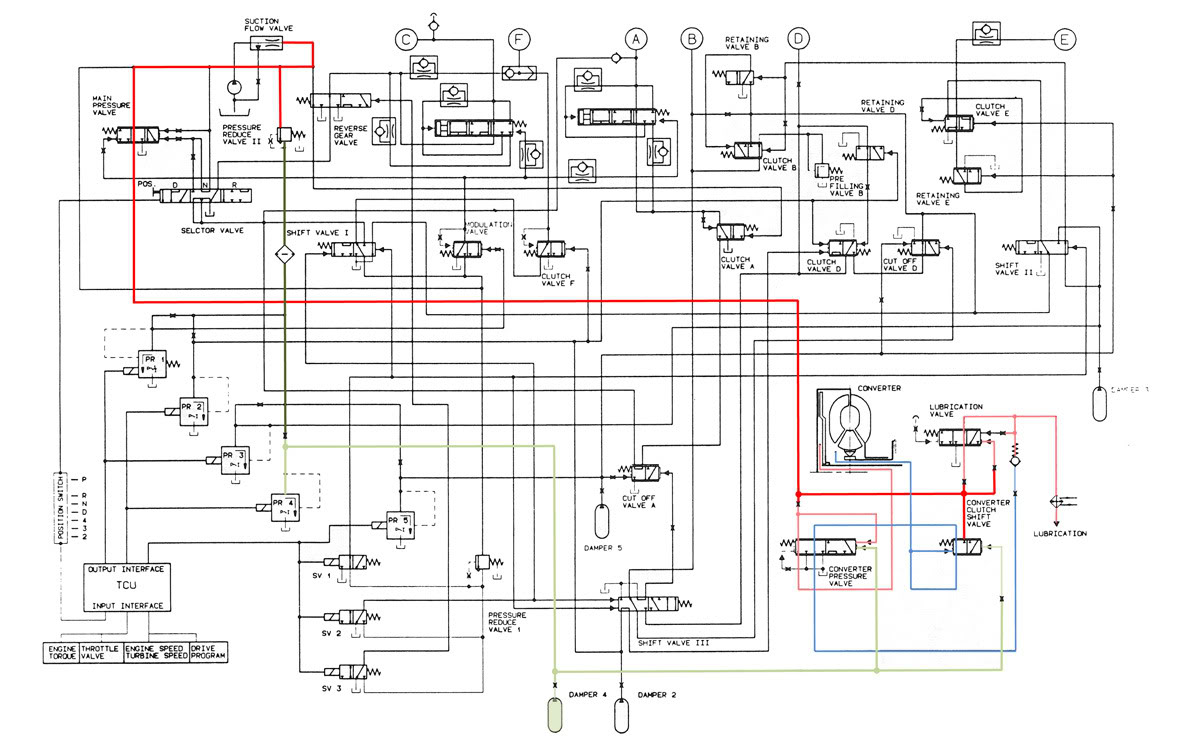
The automatic transmission experiences a judder in fifth gear only, which is more pronounced when climbing an incline. Engaging sport mode and shifting down to fourth gear eliminates this judder. After consulting a local ZF specialist, a service was performed,...