


Twisted-Pair Video Cable Driver and Receiver
#twisted-pair
#video cable
#data communication
#driver
#receiver
#coaxial-cable
#signal transmission
#wiring technique
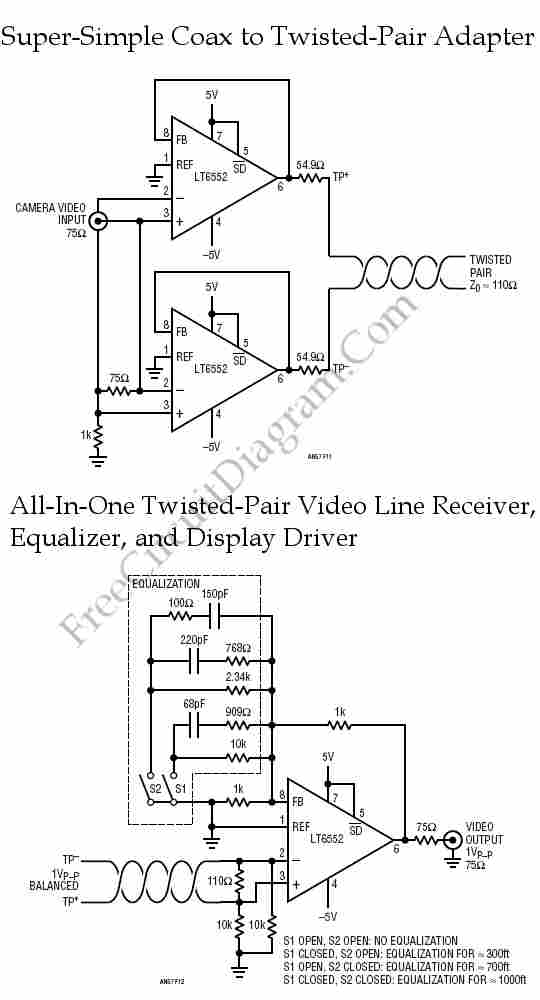
Twisted-pair wiring is a wiring technique commonly utilized for in-building data communication. Compared to conventional coaxial cable, this technique offers various advantages.
Twisted-pair wiring consists of pairs of insulated copper wires that are twisted together to form a single cable. This design helps to reduce electromagnetic interference (EMI) and crosstalk between adjacent pairs, enhancing the overall performance of data transmission. The twisting of the wires ensures that any interference affects each wire equally, allowing the differential signal to be maintained effectively.
Twisted-pair cables are categorized into two main types: unshielded twisted pair (UTP) and shielded twisted pair (STP). UTP is the most common type used in networking applications due to its cost-effectiveness and sufficient performance for most data transmission requirements. STP, on the other hand, includes additional shielding to further protect against external interference, making it suitable for environments with high levels of EMI.
The wiring technique is widely used in various applications, including local area networks (LANs), telephone systems, and other data communication systems. Categories of twisted-pair cables, such as Cat 5e, Cat 6, and Cat 6a, define the performance specifications, including bandwidth and data rate capabilities, with each successive category providing improved performance.
In summary, twisted-pair wiring is a fundamental technology in modern data communication, offering a reliable and efficient means of transmitting data over short to moderate distances within buildings. Its design and categorization allow for flexibility in application and performance, making it a preferred choice in many networking scenarios.Twisted-pair wiring is a wiring technique that usually used for in-building data communication. Compared to conventional coaxial-cable, this technique offers.
Twisted-pair wiring consists of pairs of insulated copper wires that are twisted together to form a single cable. This design helps to reduce electromagnetic interference (EMI) and crosstalk between adjacent pairs, enhancing the overall performance of data transmission. The twisting of the wires ensures that any interference affects each wire equally, allowing the differential signal to be maintained effectively.
Twisted-pair cables are categorized into two main types: unshielded twisted pair (UTP) and shielded twisted pair (STP). UTP is the most common type used in networking applications due to its cost-effectiveness and sufficient performance for most data transmission requirements. STP, on the other hand, includes additional shielding to further protect against external interference, making it suitable for environments with high levels of EMI.
The wiring technique is widely used in various applications, including local area networks (LANs), telephone systems, and other data communication systems. Categories of twisted-pair cables, such as Cat 5e, Cat 6, and Cat 6a, define the performance specifications, including bandwidth and data rate capabilities, with each successive category providing improved performance.
In summary, twisted-pair wiring is a fundamental technology in modern data communication, offering a reliable and efficient means of transmitting data over short to moderate distances within buildings. Its design and categorization allow for flexibility in application and performance, making it a preferred choice in many networking scenarios.Twisted-pair wiring is a wiring technique that usually used for in-building data communication. Compared to conventional coaxial-cable, this technique offers.
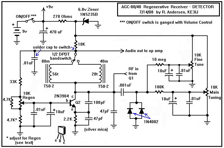
A Regenerative Receiver with AGC for 80 and 40 Meters
Here is a dual-band regenerative receiver that originated from encouraging communications with Jerry (K9UT) and another individual named Harvey, who constructed the original AGC-80 and its experimental successor, the AGC-80/30. Jerry has expressed his satisfaction with both receivers, noting their...
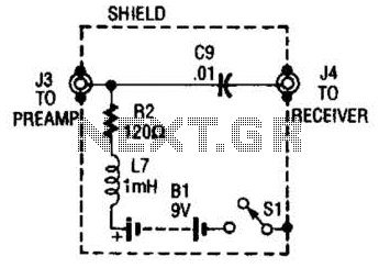
Receiver-Interface Circuit For Preamps Circuit
The purpose of the receiver/interface circuit is to pass RF to the receiver through capacitor C9, while adding DC power to the feedline through resistor R2 and RF choke L7.
The receiver/interface circuit is designed to facilitate the transmission of radio...
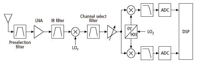
receiver architectures
Various architectures of receivers have been proposed in literature, but the most popular architectures among them, such as Heterodyne, Homodyne, Wideband-IF, and Low-IF, are presented here.
The Heterodyne receiver architecture utilizes two frequencies: the incoming radio frequency (RF) signal and a...
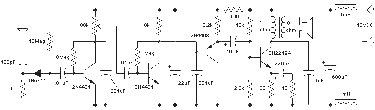
Amazing All-Band Receiver
The Amazing All-Band Receiver is essentially a diode detector followed by a high-gain audio amplifier. This device is not a multi-band receiver; it captures all signals simultaneously. The detector utilizes a biased Schottky diode for superior sensitivity and bandwidth, enabling...
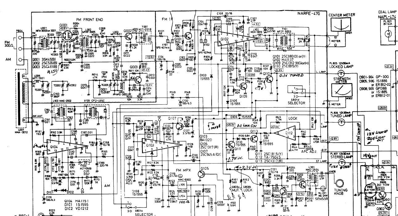
Onkyo TX2500 mk II
An Onkyo TX2500 mk II receiver is being repaired for a friend, but it is experiencing issues with both AM and FM tuning, resulting in low reception quality.
The Onkyo TX2500 mk II is a vintage audio receiver known for its...
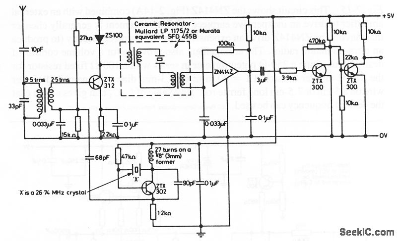
ZS100 Connection Signal
The following circuit illustrates a Noisy Regen Receiver Circuit Diagram. Features include its application in model remote-control systems and its operation as a 27-MHz superheterodyne receiver.
The Noisy Regen Receiver is a type of radio receiver that utilizes regenerative feedback to...
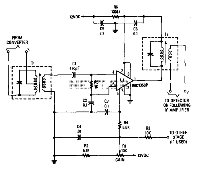
Receiver If Amplifier
Tl is tuned to the converter output frequency Ul to provide a gain of 45 to 50 dB, depending on the design of Tl and T2. C2, C3, C4, C5, and C6 function as bypass capacitors. R5 serves as a...
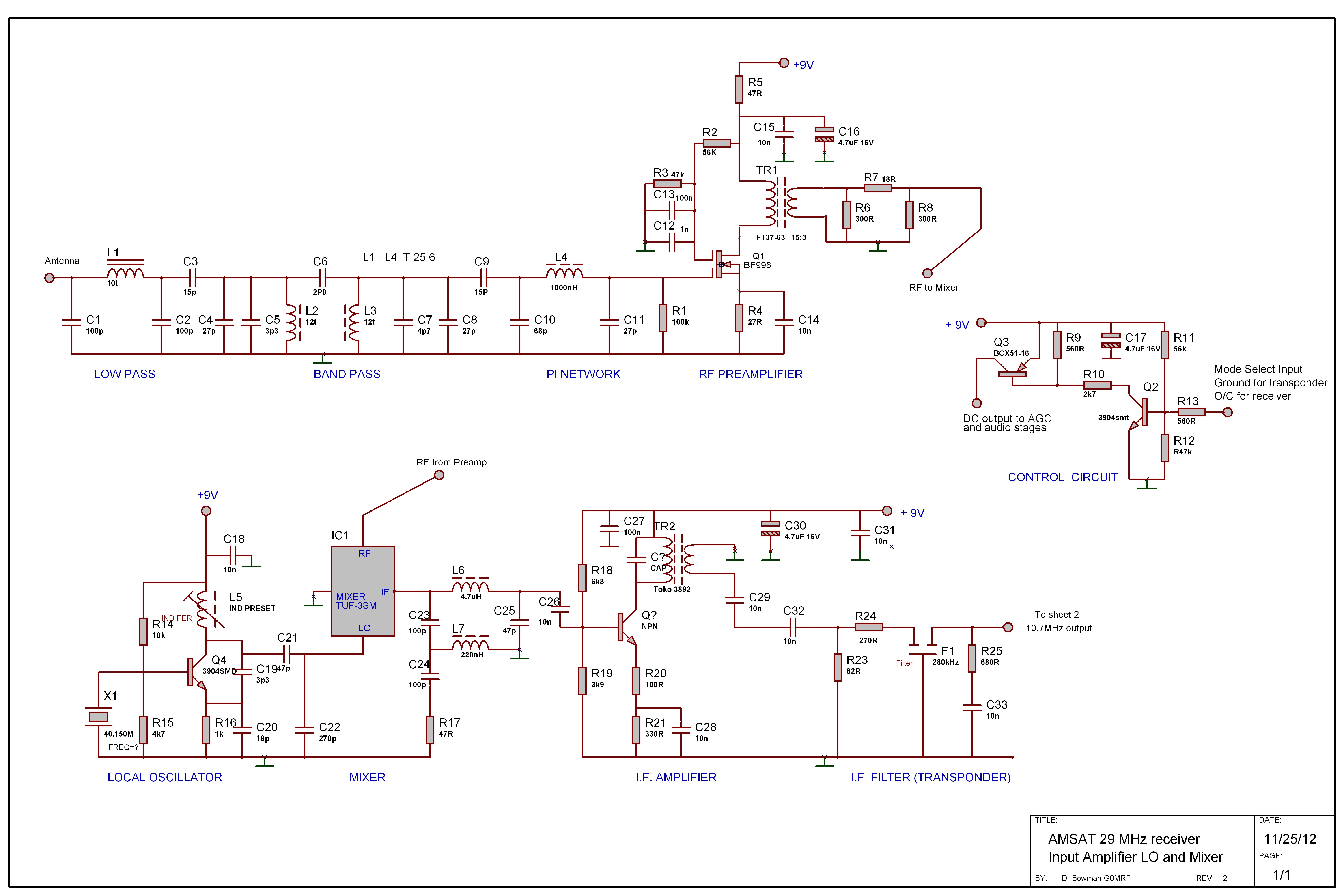
G0MRF 29.45 MHz Receiver Project
In 2007 and 2008, AMSAT-UK dedicated significant effort to a proposal for the European Space Agency (ESA) to include an Amateur Radio payload on the mass dummy during the maiden flight of the VEGA launcher. This initiative was referred to...
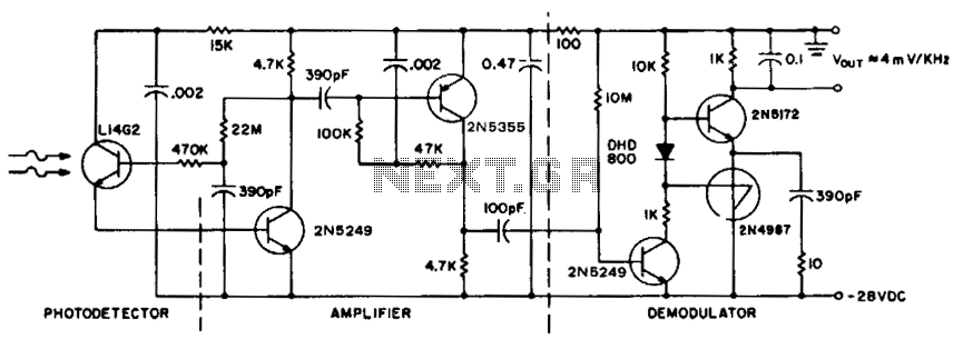
Receiver for 50 khz optical transmitter
To achieve maximum range, the receiver should be constructed similarly to a radio receiver front end, as the signals received will exhibit comparable frequency components and amplitudes of the photodiode current. The primary limitation on the receiver's performance is the...