


Simple PIC USB Interface Circuit
#PIC
#USB
#microcontroller
#LM7805
#hardware design
#communication
#power supply
#PIC 18F4455
#USB connector
Description: The hardware design for USB is quite minimal, which is advantageous. However, it quickly becomes apparent that the simplicity of the hardware design leads to complex communication and control software, which will be explored further in the theory and software sections. The primary components utilized in the circuit include the PIC 18F4455 microcontroller, a USB connector, and an LM7805 voltage regulator. The +5V output for the circuit is derived from the LM7805 regulator. It is important to note the presence of 47µF capacitors on both the input and output, which serve as DC filtering capacitors to smooth the constant DC voltage supplied to the microcontroller from the 7805 regulator. Care should be taken to verify the USB pinout, as a common error when connecting the PIC to the USB connector is reversing the D+ and D- signals. If the PIC appears to be functioning correctly but the USB device does not operate as expected, switching the D+ and D- connections may resolve the issue. The output LEDs will function as simple toggle indicators, and a program running on a laptop will enable toggling them on and off with a button press. The analog-to-digital (A/D) circuit is a standard three-pin configuration connected to power, signal output, and ground. The signal output is routed to RA0, which serves as the input for the Analog to Digital converter. Once the PIC processes this signal, it will transmit the data to the laptop via USB, allowing the laptop to visually display the value from the trimpot. A push button will provide similar functionality; when pressed, the laptop application should update to indicate the button has been activated. Although these concepts are straightforward, they become significantly more complex when implemented over USB, as will be discussed in the theory section.
The USB hardware design primarily revolves around the integration of the PIC 18F4455 microcontroller, which is responsible for processing inputs and managing communications with the laptop. The LM7805 voltage regulator ensures that the microcontroller receives a stable 5V supply, crucial for reliable operation. The 47µF capacitors are essential in filtering out any voltage spikes or noise, ensuring that the microcontroller operates smoothly without erratic behavior caused by power fluctuations.
The USB connector must be wired correctly, as the D+ and D- signals are critical for proper USB communication. A mistake in wiring can lead to the device not being recognized by the host, thus troubleshooting these connections is a fundamental step in the design process. The toggle LEDs provide visual feedback for the user, indicating the state of the outputs controlled by the microcontroller.
The A/D conversion process is vital for capturing analog signals and converting them into a digital format that can be processed by the microcontroller. The signal from the trimpot is fed into the RA0 pin, where it is converted and subsequently sent to the laptop. This data transmission is facilitated by the USB protocol, which allows for efficient and reliable communication between the microcontroller and the host computer.
In addition to the trimpot value, the push button adds interactivity to the design. The ability to notify the laptop application when the button is pressed enhances the user experience and demonstrates the capabilities of the USB interface for input handling. Overall, while the hardware design is straightforward, the integration of software and communication protocols introduces layers of complexity that are essential for achieving a functional USB device.Hardware design for USB is actually quite minimal, which is a big plus for us. However, what you quickly find out with USB is that the easy hardware design means the communication and control software is very complex, we`ll see more about that in the theory and software sections. The main devices used in the circuit are the PIC 18F4455, USB Connector and LM7805. The +5v output from the power circuit comes from the LM7805 regulator. Notice the 47uF capacitors on the input and output. These are meant to be DC filtering capacitors, which smooth out the constant DC voltage being fed to the microcontroller from the 7805 regulator. Make sure you double check your USB pinout. A common mistake when wiring the PIC to the USB connector is getting the D+ and D- signals backwards.
So if you`re sure that the PIC is running your perfect code, but the USB device isn`t coming up properly, switch D+ and D-, it might just magically fix your problem! The output LEDs will be simple `toggle` LEDs. The program running on our laptop will be able to toggle them on and off with the push of a button. The A/D circuit is a standard 3 pin, Connected to Power, Signal Out and Ground circuit. The signal output goes into RA0 which is the Analog to Digital converter. After the PIC converts this signal it should send the data to the Laptop via USB. The laptop will the visually display the trimpot`s value. The push button will do a similar thing, when the button is pushed, the laptop application should update with a notification that it has been pressed.
These are simple ideas, but when done over USB they become rather complicated as we`ll see in the theory section.
The USB hardware design primarily revolves around the integration of the PIC 18F4455 microcontroller, which is responsible for processing inputs and managing communications with the laptop. The LM7805 voltage regulator ensures that the microcontroller receives a stable 5V supply, crucial for reliable operation. The 47µF capacitors are essential in filtering out any voltage spikes or noise, ensuring that the microcontroller operates smoothly without erratic behavior caused by power fluctuations.
The USB connector must be wired correctly, as the D+ and D- signals are critical for proper USB communication. A mistake in wiring can lead to the device not being recognized by the host, thus troubleshooting these connections is a fundamental step in the design process. The toggle LEDs provide visual feedback for the user, indicating the state of the outputs controlled by the microcontroller.
The A/D conversion process is vital for capturing analog signals and converting them into a digital format that can be processed by the microcontroller. The signal from the trimpot is fed into the RA0 pin, where it is converted and subsequently sent to the laptop. This data transmission is facilitated by the USB protocol, which allows for efficient and reliable communication between the microcontroller and the host computer.
In addition to the trimpot value, the push button adds interactivity to the design. The ability to notify the laptop application when the button is pressed enhances the user experience and demonstrates the capabilities of the USB interface for input handling. Overall, while the hardware design is straightforward, the integration of software and communication protocols introduces layers of complexity that are essential for achieving a functional USB device.Hardware design for USB is actually quite minimal, which is a big plus for us. However, what you quickly find out with USB is that the easy hardware design means the communication and control software is very complex, we`ll see more about that in the theory and software sections. The main devices used in the circuit are the PIC 18F4455, USB Connector and LM7805. The +5v output from the power circuit comes from the LM7805 regulator. Notice the 47uF capacitors on the input and output. These are meant to be DC filtering capacitors, which smooth out the constant DC voltage being fed to the microcontroller from the 7805 regulator. Make sure you double check your USB pinout. A common mistake when wiring the PIC to the USB connector is getting the D+ and D- signals backwards.
So if you`re sure that the PIC is running your perfect code, but the USB device isn`t coming up properly, switch D+ and D-, it might just magically fix your problem! The output LEDs will be simple `toggle` LEDs. The program running on our laptop will be able to toggle them on and off with the push of a button. The A/D circuit is a standard 3 pin, Connected to Power, Signal Out and Ground circuit. The signal output goes into RA0 which is the Analog to Digital converter. After the PIC converts this signal it should send the data to the Laptop via USB. The laptop will the visually display the trimpot`s value. The push button will do a similar thing, when the button is pushed, the laptop application should update with a notification that it has been pressed.
These are simple ideas, but when done over USB they become rather complicated as we`ll see in the theory section.
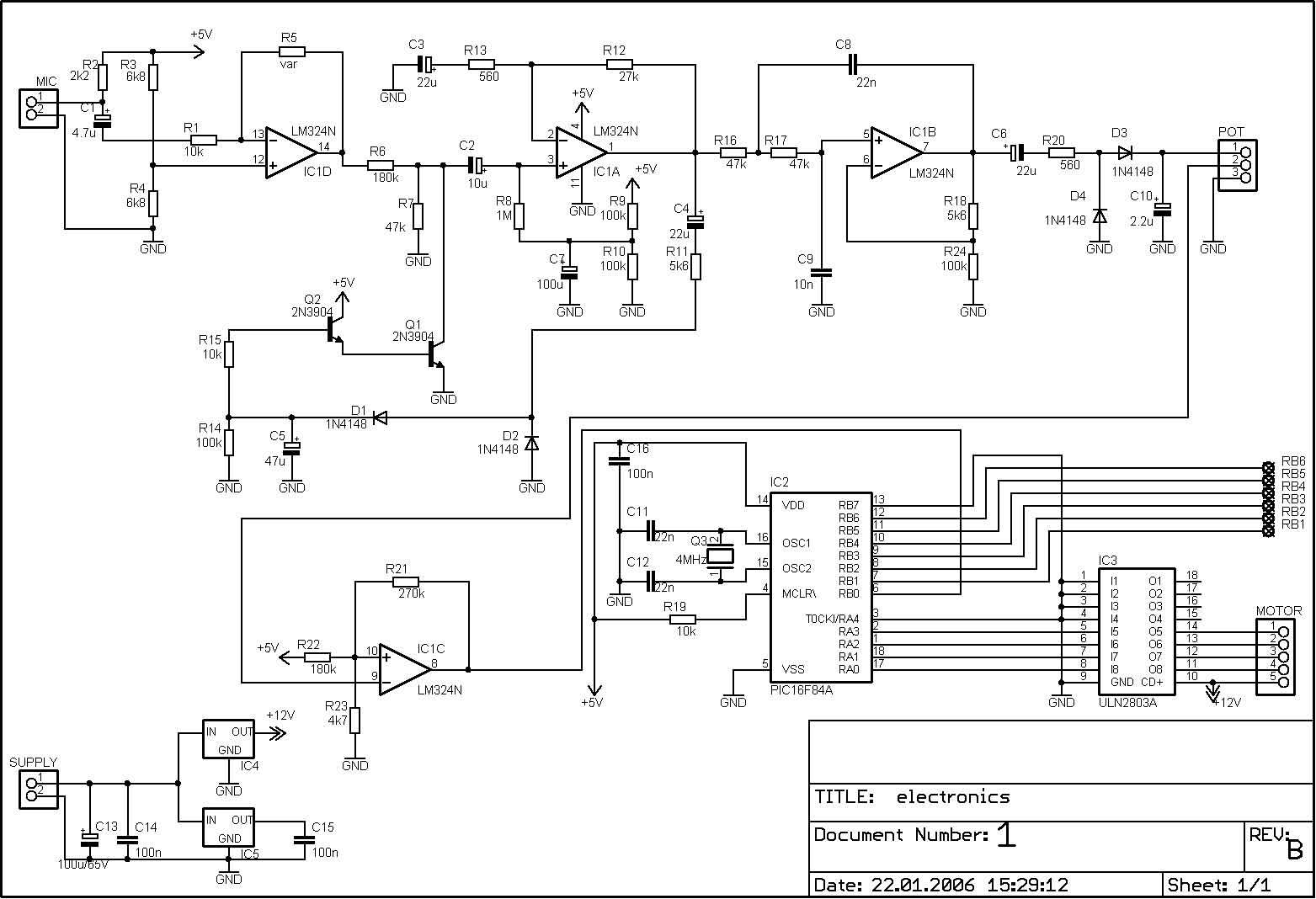
Discolight effect with bass beat control using PIC
The PIC microcontroller is capable of controlling a motor after each beat, with the option to bypass certain beats using pushbuttons. The rotation speed and duration can also be adjusted within specified limits to prevent register overflow or underflow. These...
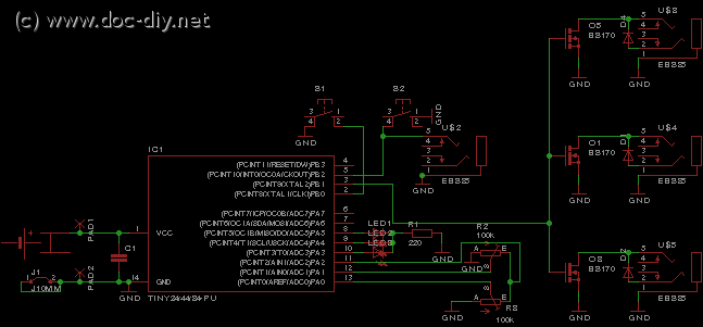
delay circuit for photography
This article outlines the construction of a simple microcontroller-based delay circuit designed for photographic applications such as drop or high-speed photography. It can control the trigger lag of cameras and flash units, generate periodic trigger pulses, or manage magnetic valves....
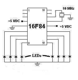
LED Chaser
This was my first successful project with a PIC chip. I used a 16F84 with a 10MHz resonator with built-in caps. Click here to view the source code to this project. The code is written in Hi-Tech C. Click here...
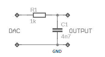
USB Audio Interface based DAC PCM2902
This weblog discusses electronic circuit schematics, PCB design, DIY kits, and electronic project diagrams. The subject circuit is a quality preamplifier with a built-in USB DAC designed for the Leachamp power amplifier. The schematic is based on the PCM2902 datasheet...
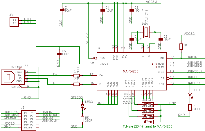
MAX3420 Maxim USB Peripheral Controller
The MAX3420 is a USB peripheral controller chip featuring an SPI bus. This document aims to provide sufficient information for effective utilization of the device in various projects. The MAX3420 simplifies the integration of a USB interface into a circuit...
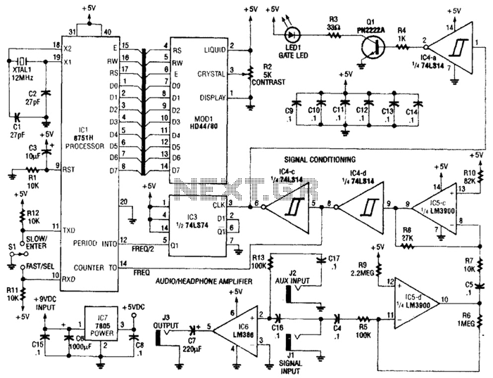
Perfect Pitch Circuit
Perfect Pitch, which is based on the 8751 microprocessor, is an affordable and straightforward instrument tuner and frequency counter that features a built-in headphone amplifier and a visual metronome. Perfect Pitch converts the audio signal from an instrument into a...
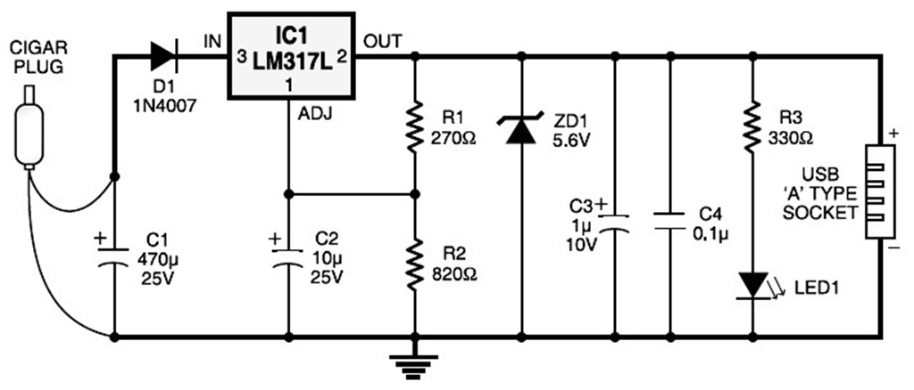
car cigar lighter to usb power socket circuit
A USB port is capable of supplying more than 100 mA of continuous electric current at 5V to peripherals connected to the bus. This feature allows a USB port to power 5V DC-operated small electronic devices without issues. Many handheld...
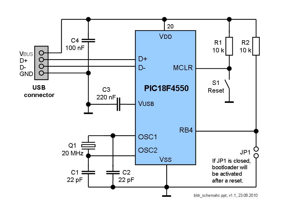
USB Bootloader
The bootloader is compatible with all USB PIC devices, including PIC18F4550, PIC18F4455, PIC18F2550, PIC18F2455, PIC18F4553, PIC18F4458, PIC18F2553, and PIC18F2458. However, since the bootloader is designed for the Microchip demo board, its configuration may not be suitable for specific projects. For...

PM4040F application circuit switching power supply drive
The PM4040F is utilized in switching power supply applications for medium power ranges. It is designed to drive power supplies between 200W and 800W, as illustrated in the accompanying bridge circuit. For power applications below 1000W, an alternative circuit configuration...