


Easy to adjust high-precision PWM pulse width modulation 12-bit DA converter
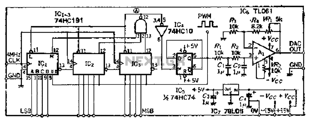
Description: A PWM clock signal is generated at 4096 times the input frequency, counting up (Q3) until the base of ICi-IC3 is full. The output point produces a maximum clock signal. On one side, voltage data is loaded into IC3, while the other side maintains a steady state in IC5. The counting process then shifts to a countdown mode until a minimum clock signal period is reached. The voltage signal on one side reloads data into ICi-ICz, while the bistable flip-flop IC5 returns to its original state and begins counting up again. This process repeats continuously. The voltage data values and the pulse count port number are used for PWM demodulation. A smoothing filter consisting of resistors R1, R2 and capacitors C1, C2 converts the signal into a DC voltage. A high input impedance operational amplifier (OP) amplifies the signal by a factor of two, resulting in a voltage range of 0 to +10V.
The described circuit functions as a pulse width modulation (PWM) generator and demodulator. The primary component, a series of integrated circuits (ICs), operates in two modes: counting up and counting down. Initially, the PWM clock signal is generated at a frequency that is 4096 times higher than the input frequency. This high-frequency signal allows for precise control over the output.
The counting mechanism is initiated by the ICi-IC3, which accumulates counts until a designated threshold is reached, at which point the output transitions to a maximum clock signal. This output is critical for maintaining synchronization with the input data. The voltage data is then loaded into IC3, while IC5 remains in a stable state, functioning as a bistable flip-flop that retains its state until prompted to change.
Once the maximum clock signal is achieved, the circuit transitions to a countdown phase. This phase continues until the minimum clock signal period is reached, indicating the end of the countdown. During this phase, the voltage signal facilitates the reloading of data into ICi-ICz, ensuring that the system can respond to new input signals efficiently.
The PWM demodulation process is integral to the operation of this circuit. The voltage data values are compared against the pulse count, allowing for accurate signal processing. The smoothing filter, composed of resistors R1 and R2 along with capacitors C1 and C2, plays a critical role in converting the PWM signal into a stable DC voltage. This conversion is essential for applications that require a steady voltage output.
Finally, the operational amplifier (OP) enhances the output signal by a factor of two, resulting in a voltage range from 0 to +10V. This amplification is particularly useful in applications where higher voltage levels are necessary for further processing or control tasks. Overall, the circuit is designed for robust performance in PWM applications, providing both high-frequency signal generation and accurate voltage regulation.4096 times the input frequency PWM clock signal, counts up (Q three ), until the base is full ICi-IC3 (sweet day), the output point d a MAX clock signal, which on the one hand the voltage data loaded into IClr rIC3, leaving the other dare steady Ics flip, Q ugly, namely, the number is in the state count down, and then began to count down until the point a fork outputs a MIN the clock signal period, the signal voltage on the one hand the data reloaded ICi ~ ICz, on the one hand to the bistable flip IC5 original state, and counts up, and thereafter repeat the above process. voltage data values and subtraction of the pulse count port number is the same liquid on PWM demodulation, the smoothing filter Ri, Rz and cl, C2 turn into a DC voltage, high input impedance amplifier OP is also magnified by 2 times and then converted into o ~ + iov voltage.
The described circuit functions as a pulse width modulation (PWM) generator and demodulator. The primary component, a series of integrated circuits (ICs), operates in two modes: counting up and counting down. Initially, the PWM clock signal is generated at a frequency that is 4096 times higher than the input frequency. This high-frequency signal allows for precise control over the output.
The counting mechanism is initiated by the ICi-IC3, which accumulates counts until a designated threshold is reached, at which point the output transitions to a maximum clock signal. This output is critical for maintaining synchronization with the input data. The voltage data is then loaded into IC3, while IC5 remains in a stable state, functioning as a bistable flip-flop that retains its state until prompted to change.
Once the maximum clock signal is achieved, the circuit transitions to a countdown phase. This phase continues until the minimum clock signal period is reached, indicating the end of the countdown. During this phase, the voltage signal facilitates the reloading of data into ICi-ICz, ensuring that the system can respond to new input signals efficiently.
The PWM demodulation process is integral to the operation of this circuit. The voltage data values are compared against the pulse count, allowing for accurate signal processing. The smoothing filter, composed of resistors R1 and R2 along with capacitors C1 and C2, plays a critical role in converting the PWM signal into a stable DC voltage. This conversion is essential for applications that require a steady voltage output.
Finally, the operational amplifier (OP) enhances the output signal by a factor of two, resulting in a voltage range from 0 to +10V. This amplification is particularly useful in applications where higher voltage levels are necessary for further processing or control tasks. Overall, the circuit is designed for robust performance in PWM applications, providing both high-frequency signal generation and accurate voltage regulation.4096 times the input frequency PWM clock signal, counts up (Q three ), until the base is full ICi-IC3 (sweet day), the output point d a MAX clock signal, which on the one hand the voltage data loaded into IClr rIC3, leaving the other dare steady Ics flip, Q ugly, namely, the number is in the state count down, and then began to count down until the point a fork outputs a MIN the clock signal period, the signal voltage on the one hand the data reloaded ICi ~ ICz, on the one hand to the bistable flip IC5 original state, and counts up, and thereafter repeat the above process. voltage data values and subtraction of the pulse count port number is the same liquid on PWM demodulation, the smoothing filter Ri, Rz and cl, C2 turn into a DC voltage, high input impedance amplifier OP is also magnified by 2 times and then converted into o ~ + iov voltage.
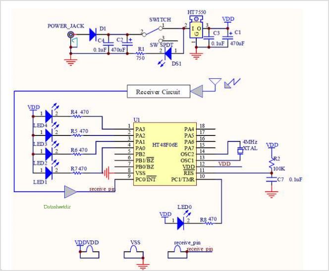
Ht48f06e Hopping Decoder
The Supertex HV440 is utilized for creating a pulse width modulated high voltage ring generator in telecommunication applications. The HV440 can function in both closed-loop and open-loop configurations. A closed-loop design, while more intricate, offers improved load regulation and lower...
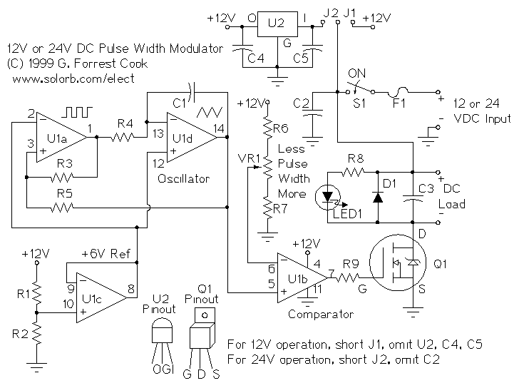
PWM Motor Speed Controller
A pulse width modulator (PWM) is a device that may be used as an efficient light dimmer or DC motor speed controller. The circuit described here is for a general purpose device that can control DC devices which draw up...
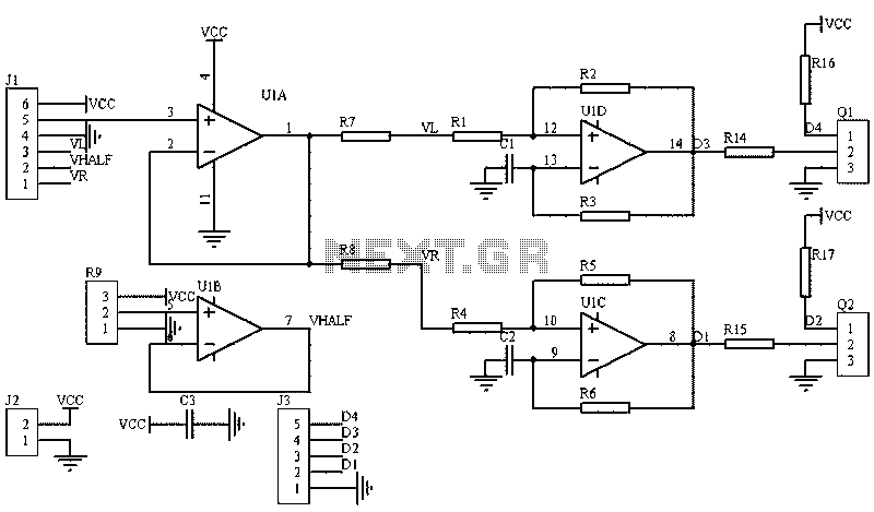
Circuit diagram of an analog circuit PWM
The image illustrates a circuit that utilizes a linear potentiometer (or linear Hall element) to control the PWM generation for two chassis drive motors in a gamepad or joystick used in model aircraft. J1 represents the handle of the potentiometer,...
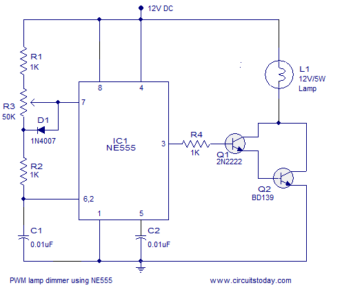
PWM lamp dimmer using NE555 timer IC. Complete circuit diagram and working
A simple PWM lamp dimmer using the NE555 timer IC. The 555 timer IC is configured as a variable duty cycle astable multivibrator to control the brightness of the lamp.
The described circuit utilizes the NE555 timer IC, a versatile and...
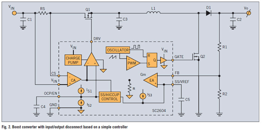
simple pwm boost converter io disconnect solves malfunctions
A PWM boost converter in a simple controller has a DC path from input VIN to VOUT, which is utilized for high-efficiency power conversion.
A PWM (Pulse Width Modulation) boost converter is an essential component in power electronics, designed to step...
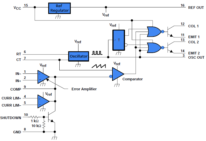
Simple PWM inverter circuit diagram using PWM chip SG3524
This document outlines a simple PWM (Pulse Width Modulation) DC to AC voltage inverter circuit based on the SG3524 integrated circuit. The SG3524 is a fixed frequency PWM voltage regulator control circuit that offers indifferent outputs suitable for both single-ended...
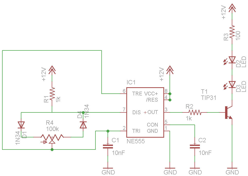
PWM tutoria
PWM circuits are versatile. They can be used to dim LEDs, regulate the speed of fans and motors, control the power supplied to thermoelectric coolers, or manage the power to nearly any device. It is essential to ensure that the...
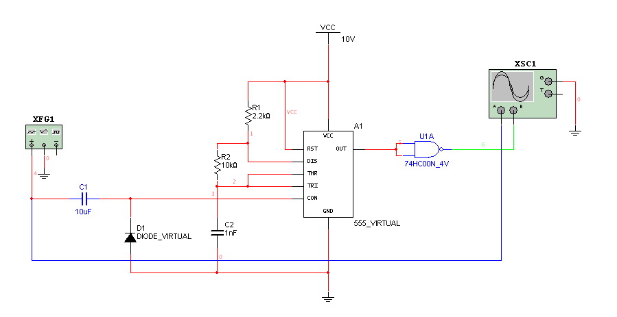
really need help on PWM and PPM circuit
Hello everyone. I need some help. I have constructed a PWM and PPM circuit. The output is functioning smoothly, but I am experiencing some problems and I am not very experienced.
The PWM (Pulse Width Modulation) and PPM (Pulse Position Modulation)...
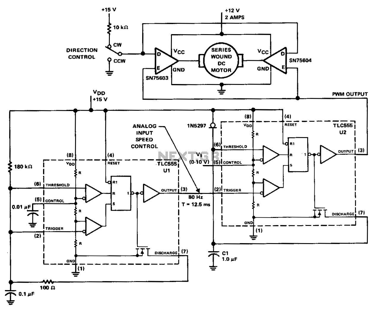
Pwm-motor-controller
The PWM controller utilizes complementary half-H peripheral drivers SN75603 and SN75604, featuring totem-pole outputs rated at 40 V and 2.0 A. These drivers effectively configure the motor in a full-bridge setup, enabling bidirectional control. Timer U1 operates in astable mode...