


Automatic Room Power ControlCircuit CD4017 IC
#CD4017
#NE555
#LDR
#automatic control
#power control
#sensor circuit
#timer
#light sensing
#energy saving
#room automation
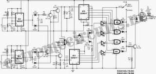
Description: The following circuit illustrates an Automatic Room Power Control Circuit Diagram. This circuit is based on the NE555 integrated circuit (IC). Features include the use of two Light Dependent Resistors (LDRs).
The Automatic Room Power Control Circuit utilizes an NE555 timer IC configured in a monostable or astable mode, depending on the desired functionality. The primary purpose of this circuit is to automatically control the power supply to a room based on ambient light levels detected by the LDRs.
In this circuit, two LDRs are strategically placed to sense the light intensity from different angles or areas within the room. As the light intensity changes, the resistance of the LDRs varies, which in turn affects the voltage at the input of the NE555 timer. When the light level drops below a certain threshold, the NE555 activates an output that can control a relay or a transistor, thereby switching on the power to the room's lighting or other electrical devices.
The circuit may include additional components such as resistors and capacitors to set the timing intervals and to stabilize the voltage levels. The output stage typically consists of a relay that can handle higher current loads, allowing for the control of multiple devices without overloading the NE555.
This circuit is ideal for energy-saving applications, ensuring that lights are turned on only when necessary and automatically switching off when sufficient natural light is available, thereby conserving electricity and enhancing convenience in everyday usage.The following circuit shows about Automatic Room Power Control Circuit Diagram. This circuit based on the NE555 IC. Features: uses two LDRs, use ..
The Automatic Room Power Control Circuit utilizes an NE555 timer IC configured in a monostable or astable mode, depending on the desired functionality. The primary purpose of this circuit is to automatically control the power supply to a room based on ambient light levels detected by the LDRs.
In this circuit, two LDRs are strategically placed to sense the light intensity from different angles or areas within the room. As the light intensity changes, the resistance of the LDRs varies, which in turn affects the voltage at the input of the NE555 timer. When the light level drops below a certain threshold, the NE555 activates an output that can control a relay or a transistor, thereby switching on the power to the room's lighting or other electrical devices.
The circuit may include additional components such as resistors and capacitors to set the timing intervals and to stabilize the voltage levels. The output stage typically consists of a relay that can handle higher current loads, allowing for the control of multiple devices without overloading the NE555.
This circuit is ideal for energy-saving applications, ensuring that lights are turned on only when necessary and automatically switching off when sufficient natural light is available, thereby conserving electricity and enhancing convenience in everyday usage.The following circuit shows about Automatic Room Power Control Circuit Diagram. This circuit based on the NE555 IC. Features: uses two LDRs, use ..
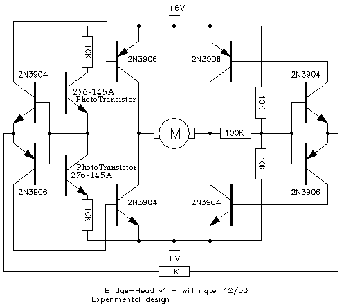
Bridge Head
The LDRs were hand-picked. Got two packages of them from Radio Shack, looking for at least two pairs of similar parts. Then added wire-wrap pin sockets to the circuit so that the LDRs could be plugged in. Currently, the 0.33µF...
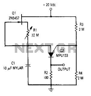
Long duration timer
The time circuit can provide a time delay of up to 20 minutes. The circuit is a standard relaxation oscillator with a FET current source in which resistor R1 is used to provide reverse bias on the gate-to-source of the...
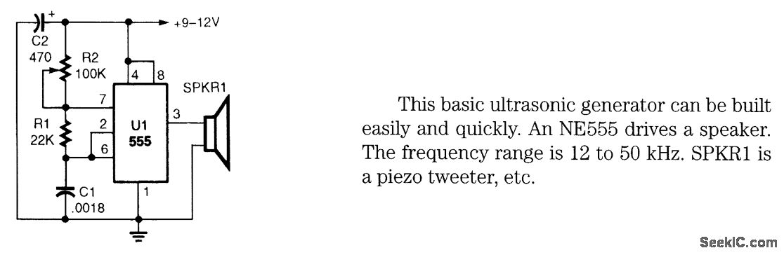
SIMPLE ULTRASONIC GENERATOR
This basic ultrasonic generator can be built easily and quickly. An NE555 drives a speaker. The frequency range is 12 to 50 kHz. SPKRI is a piezo tweeter.
The ultrasonic generator circuit utilizes the NE555 timer integrated circuit, which is configured...
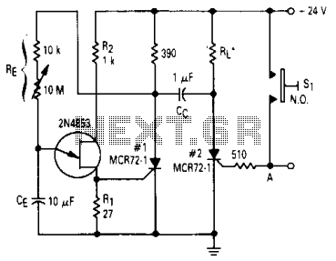
Timer circuit
After one cycle of operation, SCR1 will be activated, resulting in a low voltage being applied to the UJT emitter circuit, which interrupts the tuning function. When pushbutton SI is pressed, or a positive pulse is applied at point A,...
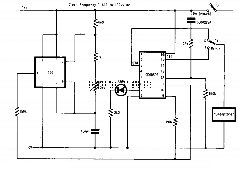
Timer with alarm
The circuit features two timing ranges: from 10 seconds to 5 minutes and from 1 minute to 80 minutes. It is powered by a 9-V battery. An LED is connected in a manner that allows for a consistent flashing frequency...
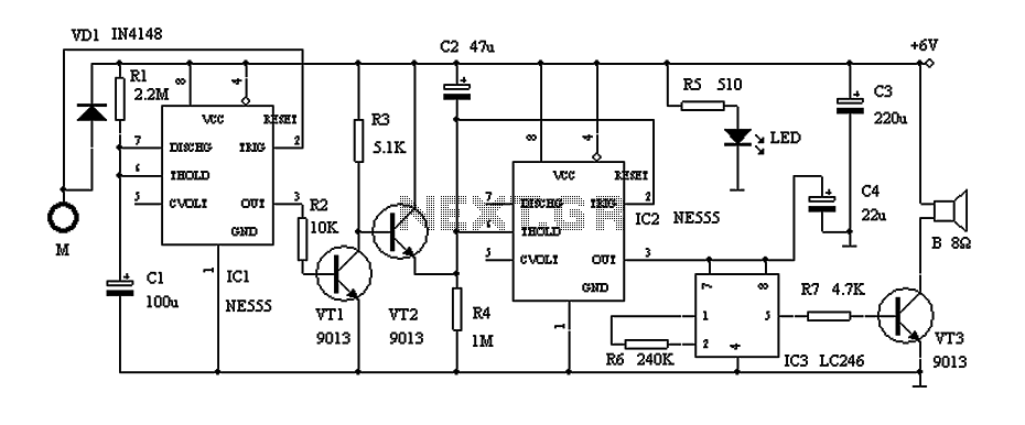
Door alarm circuit with a time of recognition NE555
This circuit describes a door alarm system equipped with a time recognition feature. When the owner opens the door, it remains in a normal state for approximately 30 seconds without triggering the alarm. However, if the door is opened by...
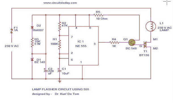
FlasherCircuit using NE 555 IC for Lamp
This circuit diagram represents a lamp flasher powered by mains electricity. It is capable of flashing lamps with a maximum power of 200 Watts at user-defined rates. The NE555 integrated circuit is configured as an astable multivibrator, generating the pulses...
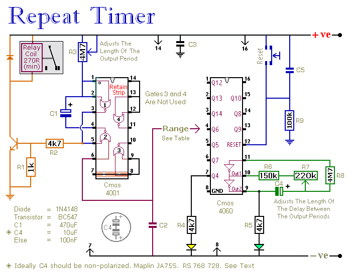
a regularly repeating interval timer
This circuit features an adjustable output timer capable of re-triggering at specified intervals. The output duration can range from a fraction of a second to over half an hour, and it can be configured to repeat at regular intervals spanning...
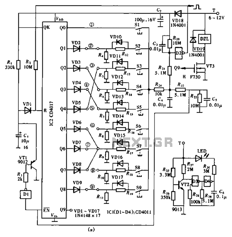
Super lock circuit diagram
The lock circuit utilizes a decimal counter CD4017, which consists of ten output terminals. These terminals are connected through a combination that corresponds to a group of passwords, allowing for a maximum of up to 100 million combinations, hence referred...