


Bluetooth Based Smart HomeCircuit Based On The ULN2003 IC
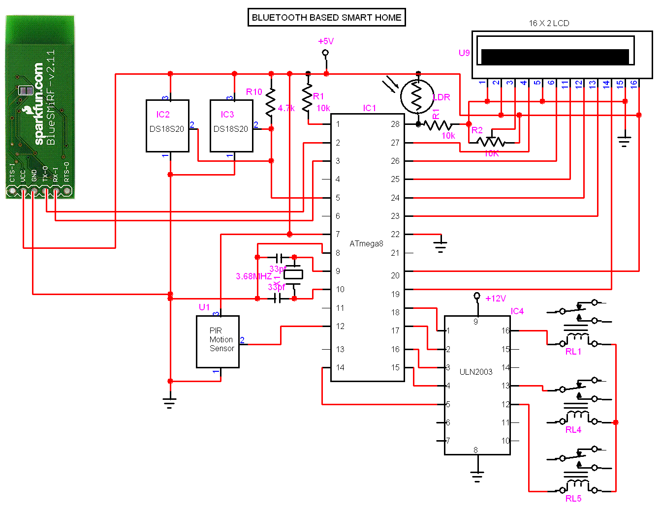
Description: The following circuit illustrates a Bluetooth-based smart home circuit diagram. This circuit is based on the ULN2003 integrated circuit (IC). Features include an LCD and LED.
The Bluetooth-based smart home circuit utilizes the ULN2003 IC, which is a high-voltage, high-current Darlington transistor array. This IC is instrumental in driving various loads such as LEDs and relays, making it suitable for controlling home appliances through Bluetooth communication. The circuit can be divided into several key components: the Bluetooth module, the ULN2003 IC, the LCD display, and the LED indicators.
The Bluetooth module, typically an HC-05 or HC-06, facilitates wireless communication between a smartphone or computer and the smart home circuit. This allows users to send commands to control various devices remotely. The module is connected to a microcontroller, which interprets the received Bluetooth signals and sends appropriate control signals to the ULN2003.
The ULN2003 is connected to the microcontroller's output pins, and it can control multiple devices simultaneously. Each output pin of the ULN2003 can drive up to 500 mA of current, making it capable of handling various loads such as light bulbs or small motors. The inputs of the ULN2003 are connected to the microcontroller, which sends a high signal to activate the corresponding output pin.
The LCD display serves as a user interface, providing real-time feedback on the status of the connected devices. It can display messages such as "Device On" or "Device Off," allowing users to monitor their home appliances easily. The LCD is interfaced with the microcontroller using a 4-bit or 8-bit configuration, depending on the desired complexity and number of connections.
LED indicators can be incorporated into the circuit to visually represent the status of the devices being controlled. For example, a green LED can indicate that a device is powered on, while a red LED can signal that it is off. The LEDs are connected to the output pins of the ULN2003 and are activated based on the signals from the microcontroller.
In summary, the Bluetooth-based smart home circuit diagram demonstrates a practical application of the ULN2003 IC in controlling home appliances through wireless communication, with the added functionality of an LCD display for user interaction and LED indicators for device status visualization. This circuit provides an efficient and user-friendly solution for modern smart home automation.The following circuit shows about Bluetooth Based Smart Home Circuit Diagram. This circuit based on the ULN2003 IC. Features: LCD & LED ..
The Bluetooth-based smart home circuit utilizes the ULN2003 IC, which is a high-voltage, high-current Darlington transistor array. This IC is instrumental in driving various loads such as LEDs and relays, making it suitable for controlling home appliances through Bluetooth communication. The circuit can be divided into several key components: the Bluetooth module, the ULN2003 IC, the LCD display, and the LED indicators.
The Bluetooth module, typically an HC-05 or HC-06, facilitates wireless communication between a smartphone or computer and the smart home circuit. This allows users to send commands to control various devices remotely. The module is connected to a microcontroller, which interprets the received Bluetooth signals and sends appropriate control signals to the ULN2003.
The ULN2003 is connected to the microcontroller's output pins, and it can control multiple devices simultaneously. Each output pin of the ULN2003 can drive up to 500 mA of current, making it capable of handling various loads such as light bulbs or small motors. The inputs of the ULN2003 are connected to the microcontroller, which sends a high signal to activate the corresponding output pin.
The LCD display serves as a user interface, providing real-time feedback on the status of the connected devices. It can display messages such as "Device On" or "Device Off," allowing users to monitor their home appliances easily. The LCD is interfaced with the microcontroller using a 4-bit or 8-bit configuration, depending on the desired complexity and number of connections.
LED indicators can be incorporated into the circuit to visually represent the status of the devices being controlled. For example, a green LED can indicate that a device is powered on, while a red LED can signal that it is off. The LEDs are connected to the output pins of the ULN2003 and are activated based on the signals from the microcontroller.
In summary, the Bluetooth-based smart home circuit diagram demonstrates a practical application of the ULN2003 IC in controlling home appliances through wireless communication, with the added functionality of an LCD display for user interaction and LED indicators for device status visualization. This circuit provides an efficient and user-friendly solution for modern smart home automation.The following circuit shows about Bluetooth Based Smart Home Circuit Diagram. This circuit based on the ULN2003 IC. Features: LCD & LED ..
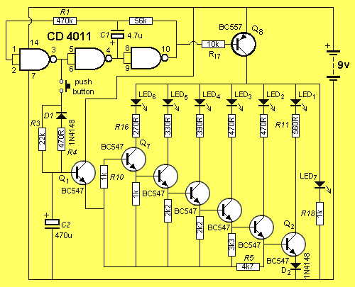
up down led sequencer
A 10-light LED bar graph is desired, where the LEDs light up sequentially until all are lit, then cycle back down until all are off. The LM3914 - Dot/Bar Display Driver is a simpler analog solution that operates in bar...
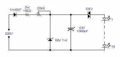
LED Flasher IV
This circuit will flash a string of LEDs, typically 16, with direct connection to the mains and with a period adjustable between 1 and 4 seconds depending on the setting of the 22K/1W pot. Operation at 110V should also be...
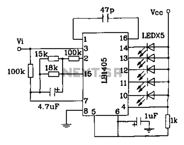
LED indication Integrated Circuits
The LB140 is depicted in Figure as a typical driver IC circuit for a five-digit LED level indicator. The BL1405 is commonly utilized in tape recorders for level indication.
The LB140 integrated circuit serves as a driver for five-digit LED displays,...
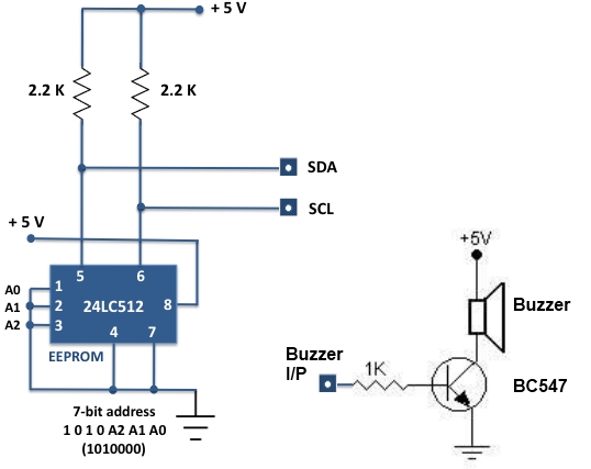
Experimental I/O board for microcontrollers
For beginners experiencing similar challenges, a general-purpose I/O board is recommended to minimize prototyping time and maximize space on the breadboard for projects. The construction of this board is straightforward. Basic I/O devices can be soldered onto a general-purpose perforated...
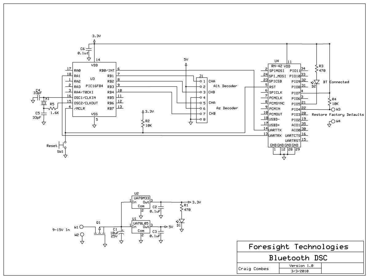
Bluetooth Digital Setting Circles
This variation of the Digital Setting Circles project was developed by Craig Combes, who shared his insights for others to replicate his version. Many users utilize Dave's serial DSC board along with a serial to Bluetooth adapter, which can be...

High Volt LED Flasher
This circuit is a Flasher that directly derives power from AC to produce brilliant flashes at a rate of one flash per second. It utilizes a Diac as the primary element.
The Flasher circuit operates by converting alternating current (AC) into...
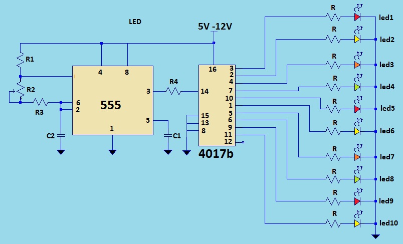
LED light chaser using 4017
This is a LED sequencer circuit where 10 LEDs light up and turn off sequentially, creating a chasing effect. This simple circuit is suitable for designing lighting decorations on Christmas trees. It can also be used for lighting animations by...
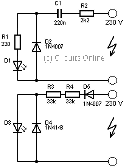
230volt led circuit
This circuit is used to power an LED with a voltage of 230V. The 230V must be reduced to meet the LED's voltage requirements. To achieve this, a circuit is necessary as described below.
The circuit designed to power an LED...
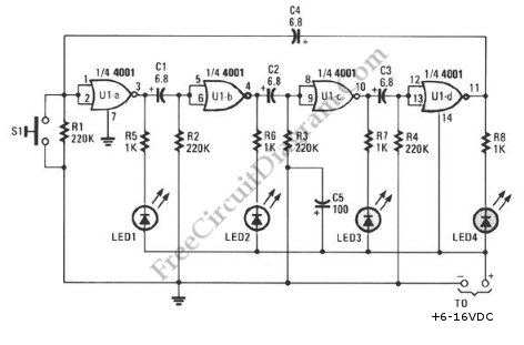
Ring-Around LED Flasher
This schematic diagram illustrates a ring-around LED flasher circuit. The circuit operates by turning off two LEDs while activating the other two, continuing this pattern until the timing cycle reverses.
The ring-around LED flasher circuit is designed to create a visually...