


Ir Heat-Controlled Kitchen Fan
#IR sensor
#heat detection
#fan control
#optocoupler
#switching circuit
#automation
#kitchen appliance
#temperature control
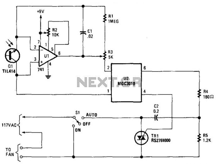
Description: Q1 senses infrared radiation from heat sources, which causes U1 to switch on, activating optocoupler U1 and triggering TRIAC TR1. This controls a fan. The TRIAC can be sourced from Radio Shack or a 200-V, 6-A unit (C106B) can be used.
The circuit operates by utilizing an infrared (IR) sensor, designated as Q1, which detects the presence of heat sources. Upon detecting IR radiation, Q1 generates an output signal that activates the control circuit. The component U1 serves as a switching device, which, when energized by Q1, allows current to flow to the optocoupler U1. The optocoupler is critical for isolating the control side of the circuit from the high-voltage side, ensuring safety and preventing damage to sensitive components.
Once the optocoupler is activated, it sends a signal to TRIAC TR1. The TRIAC functions as a switch that can control the power delivered to the fan. When TR1 is triggered, it allows current to flow through the fan, activating it and providing cooling as needed. The choice of TRIAC is essential; a suitable component, such as a 200-V, 6-A TRIAC (C106B) or similar from Radio Shack, is recommended for this application to ensure it can handle the power requirements of the fan.
This circuit design is efficient for applications where automated cooling is required in response to heat detection, such as in HVAC systems or electronic device cooling solutions. The use of an optocoupler not only provides isolation but also enhances the reliability of the system by protecting the low-voltage control circuitry from high-voltage spikes that may occur when the TRIAC is activated. Overall, this combination of components creates a robust solution for controlling fan operation based on thermal input. Ql senses IR from heat sources, causes U1 to switch, activates optocopuler Ul, and triggers TR1. This contro ls a fan. The Triac is from Radio Shack, or else a 200-V, 6-A unit (C106B) can be used.
The circuit operates by utilizing an infrared (IR) sensor, designated as Q1, which detects the presence of heat sources. Upon detecting IR radiation, Q1 generates an output signal that activates the control circuit. The component U1 serves as a switching device, which, when energized by Q1, allows current to flow to the optocoupler U1. The optocoupler is critical for isolating the control side of the circuit from the high-voltage side, ensuring safety and preventing damage to sensitive components.
Once the optocoupler is activated, it sends a signal to TRIAC TR1. The TRIAC functions as a switch that can control the power delivered to the fan. When TR1 is triggered, it allows current to flow through the fan, activating it and providing cooling as needed. The choice of TRIAC is essential; a suitable component, such as a 200-V, 6-A TRIAC (C106B) or similar from Radio Shack, is recommended for this application to ensure it can handle the power requirements of the fan.
This circuit design is efficient for applications where automated cooling is required in response to heat detection, such as in HVAC systems or electronic device cooling solutions. The use of an optocoupler not only provides isolation but also enhances the reliability of the system by protecting the low-voltage control circuitry from high-voltage spikes that may occur when the TRIAC is activated. Overall, this combination of components creates a robust solution for controlling fan operation based on thermal input. Ql senses IR from heat sources, causes U1 to switch, activates optocopuler Ul, and triggers TR1. This contro ls a fan. The Triac is from Radio Shack, or else a 200-V, 6-A unit (C106B) can be used.
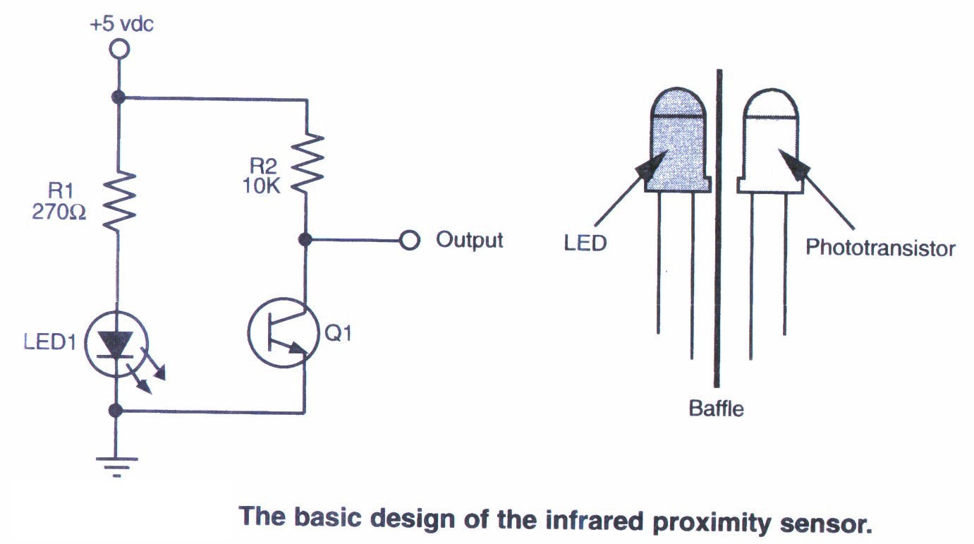
ir sensor
This section provides step-by-step instructions along with images for constructing an infrared (IR) proximity switch. As this is a straightforward circuit, only the schematic for the sensor is presented here. The objective of this tutorial is to assist others in...
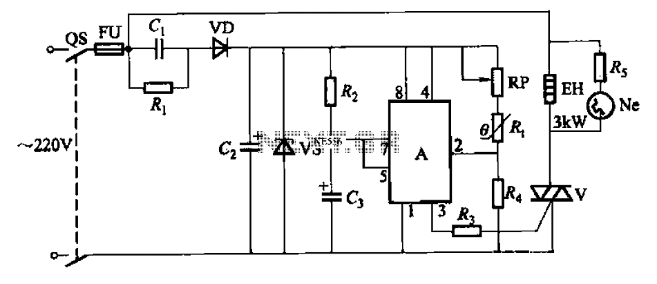
Automatic temperature control circuit
An automatic temperature control circuit is designed for climate control thermostats. Its primary function is to maintain a constant internal temperature using an electric heater (EH). The control mechanism utilizes a negative temperature coefficient thermistor as the temperature sensing element,...
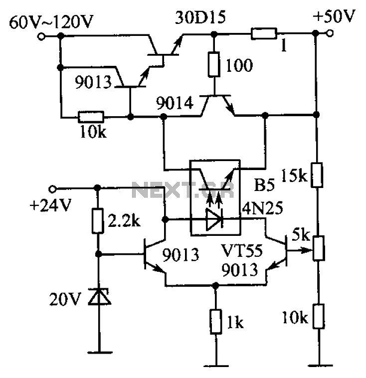
High voltage stabilizing circuit diagram composed of optocouplers
The circuit is illustrated. A standard driving transistor requires a higher breakdown voltage transistor (such as the FIG driving tube 9013). As the output voltage rises, the bias on VT55 increases, leading to an increase in the forward current of...
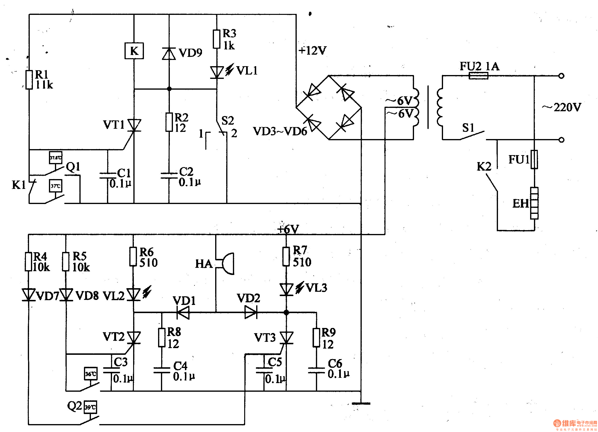
Eggs hatching incubator circuit diagram 4
The egg hatching incubator circuit comprises a power supply circuit, a constant temperature control circuit, and a sound and light alarm circuit, as illustrated in Figure 4-7. The power supply circuit includes a power switch (S1), a fuse (FU2), a...
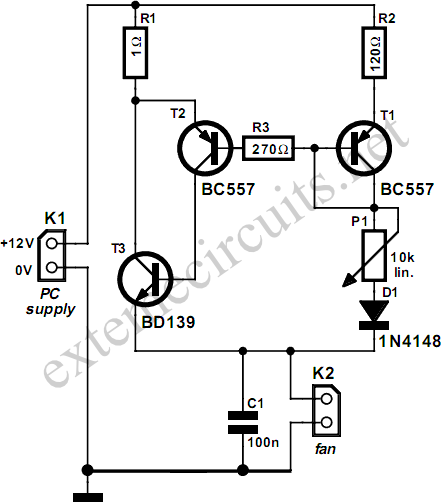
Processor Fan Control
Fans in PCs can be excessively loud. In many instances, the noise generated by the fan can be significantly reduced by decreasing its speed. Although this reduction will lower the cooling capacity, it does not pose a problem as long...
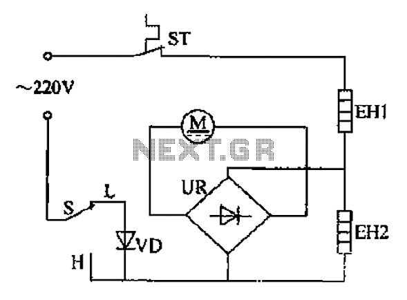
Comb electric circuit
The comb electric circuit illustrated in Figure 1-3 features two temperature settings. By toggling switch S to either the L or H position, different temperatures can be achieved. Once switch S is activated, the circuit powers the heating wires EH1...
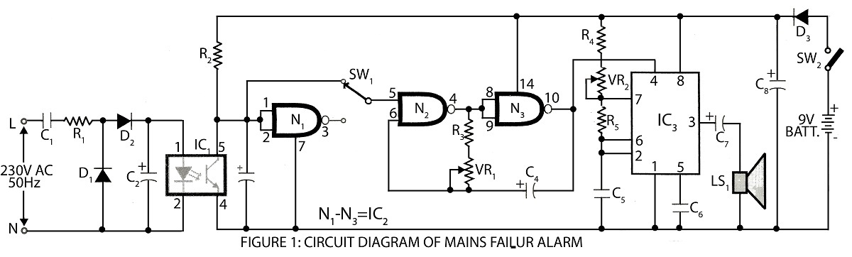
Digital Mains Failure/Resumption Alarm
A digital mains failure and resumption alarm circuit utilizes an optocoupler to generate an audible sound. This circuit diagram includes a description of various alarm circuits for digital mains failure.
The digital mains failure and resumption alarm circuit is designed to...
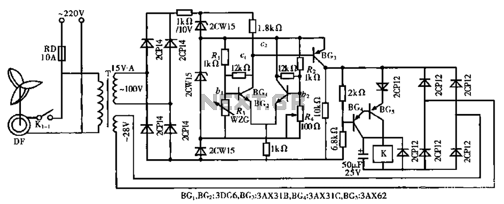
Fan automatic control circuit
The circuit is a bistable circuit where each bistable unit is controlled by high and low output levels. When power is supplied to the circuit, current flows through components R13, CL, and VD to VD2 for full-wave rectification. The ZD...
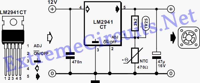
PC Fan Speed Controller - For a Low-Noise PC
The fan operates continuously in many PCs, which may not be necessary. A simple controller circuit can adjust the fan speed based on demand. This not only conserves energy but also minimizes noise irritation from the fan. Only three components...