


9V to 5V converter schematic with 555
#555 timer
#voltage converter
#negative voltage
#zener diode
#squarewave
#capacitor
#diode
#9V to 5V
#voltage regulator
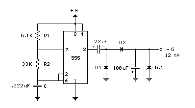
Description: A 555 timer can be used to generate a square wave to produce a negative voltage relative to the negative battery terminal. When the timer output at pin 3 goes positive, the series 22 uF capacitor charges through the diode (D1) to about 8 volts. When the output switches to ground, the 22 uF cap discharges through the second diode (D2) and charges the 100 uF capacitor to a negative voltage. The negative voltage can rise over several cycles to about -7 volts but is limited by the 5.1 volt zener diode which serves as a regulator. Circuit draws about 6 milliamps from the battery without the zener diode connected and about 18 milliamps connected. Output current available for the load is about 12 milliamps. An additional 5.1 volt zener and 330 ohm resistor could be used to regulate the +9 down to +5 at 12 mA if a symmetrical +/- 5 volt supply is needed. The battery drain would then be around 30 mA.
The circuit utilizes a 555 timer configured in astable mode to generate a square wave output. The output from pin 3 of the 555 timer alternates between high and low states, which is instrumental in charging and discharging the capacitors involved in the circuit. Initially, when the output is high, the 22 µF capacitor (C1) charges through diode D1, allowing it to reach approximately 8 volts. This charging phase is critical for establishing the necessary potential difference for generating the negative voltage.
When the output switches to a low state, the 22 µF capacitor discharges through diode D2. This action allows the capacitor to transfer its stored energy to the 100 µF capacitor (C2), creating a negative voltage relative to the negative terminal of the battery. The circuit is designed to allow the negative voltage to accumulate over several cycles, potentially reaching around -7 volts. However, this negative voltage is regulated by a 5.1-volt zener diode (Z1), which prevents the voltage from exceeding safe levels.
The overall current consumption of the circuit is approximately 6 milliamps when the zener diode is not connected. With the zener diode in place, the current draw increases to about 18 milliamps. The output current available for driving a load is around 12 milliamps, indicating that the circuit is capable of powering small devices or components.
For applications requiring a symmetrical power supply, an additional 5.1-volt zener diode and a 330-ohm resistor can be integrated into the circuit. This configuration would allow regulation of the +9 volts down to +5 volts at 12 milliamps, thereby providing a dual supply of +5 volts and -5 volts. The inclusion of this additional regulation would increase the battery drain to approximately 30 milliamps, necessitating consideration of battery capacity and longevity in the design of the overall system.A 555 timer can be used to generate a squarewave to produce a negative voltage relative to the negative battery terminal. When the timer output at pin 3 goes positive, the series 22 uF capacitor charges through the diode (D1) to about 8 volts.
When the output switches to ground, the 22 uF cap discharges through the second diode (D2) and charges the 100 uF capacitor to a negative voltage. The negative voltage can rise over several cycles to about -7 volts but is limited by the 5.1 volt zener diode which serves as a regulator.
Circuit draws about 6 milliamps from the battery without the zener diode connected and about 18 milliamps connected. Output current available for the load is about 12 milliamps. An additional 5.1 volt zener and 330 ohm resistor could be used to regulate the +9 down to +5 at 12 mA if a symmetrical +/- 5 volt supply is needed.
The battery drain would then be around 30 mA.
The circuit utilizes a 555 timer configured in astable mode to generate a square wave output. The output from pin 3 of the 555 timer alternates between high and low states, which is instrumental in charging and discharging the capacitors involved in the circuit. Initially, when the output is high, the 22 µF capacitor (C1) charges through diode D1, allowing it to reach approximately 8 volts. This charging phase is critical for establishing the necessary potential difference for generating the negative voltage.
When the output switches to a low state, the 22 µF capacitor discharges through diode D2. This action allows the capacitor to transfer its stored energy to the 100 µF capacitor (C2), creating a negative voltage relative to the negative terminal of the battery. The circuit is designed to allow the negative voltage to accumulate over several cycles, potentially reaching around -7 volts. However, this negative voltage is regulated by a 5.1-volt zener diode (Z1), which prevents the voltage from exceeding safe levels.
The overall current consumption of the circuit is approximately 6 milliamps when the zener diode is not connected. With the zener diode in place, the current draw increases to about 18 milliamps. The output current available for driving a load is around 12 milliamps, indicating that the circuit is capable of powering small devices or components.
For applications requiring a symmetrical power supply, an additional 5.1-volt zener diode and a 330-ohm resistor can be integrated into the circuit. This configuration would allow regulation of the +9 volts down to +5 volts at 12 milliamps, thereby providing a dual supply of +5 volts and -5 volts. The inclusion of this additional regulation would increase the battery drain to approximately 30 milliamps, necessitating consideration of battery capacity and longevity in the design of the overall system.A 555 timer can be used to generate a squarewave to produce a negative voltage relative to the negative battery terminal. When the timer output at pin 3 goes positive, the series 22 uF capacitor charges through the diode (D1) to about 8 volts.
When the output switches to ground, the 22 uF cap discharges through the second diode (D2) and charges the 100 uF capacitor to a negative voltage. The negative voltage can rise over several cycles to about -7 volts but is limited by the 5.1 volt zener diode which serves as a regulator.
Circuit draws about 6 milliamps from the battery without the zener diode connected and about 18 milliamps connected. Output current available for the load is about 12 milliamps. An additional 5.1 volt zener and 330 ohm resistor could be used to regulate the +9 down to +5 at 12 mA if a symmetrical +/- 5 volt supply is needed.
The battery drain would then be around 30 mA.
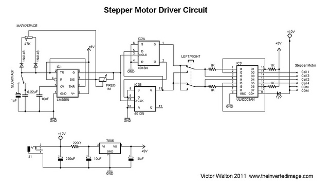
DIY video dolly stepper motor driver
The commonly used 555 timer is configured for a variable mark/space ratio, which is essential for this application. Additionally, two D-type flip-flops (4013) are employed to provide the necessary count for the ULN2003 stepper motor driver. ULN2003 components may be...
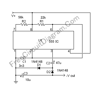
Simple 555 Switching Circuit Provides Negative Supply from Single Positive Supply
If a negative supply is required for an operational amplifier or if a negative bias voltage is needed while operating from a single supply voltage, such as in battery applications.
To generate a negative supply voltage from a single positive supply,...
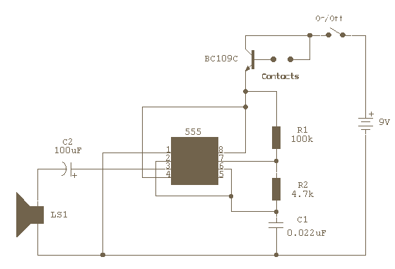
Water Activated Alarm
The circuit uses a 555 timer wired as an astable oscillator and powered by the emitter current of the BC109C. Under dry conditions, the transistor will have no bias current and be fully off. As the probes get wet, a...
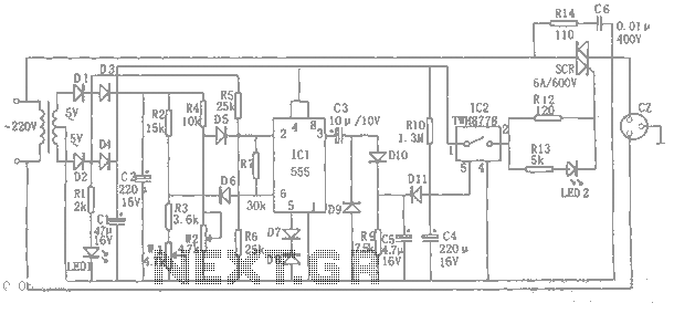
555 automatic power-protection circuit diagram
An automatic power protection circuit is presented. This protection includes a step-down rectifier circuit, an overvoltage and undervoltage detection circuit, and a delay switch control circuit. The step-down circuit is responsible for the entire rectifier circuit's DC voltage.
The automatic power...
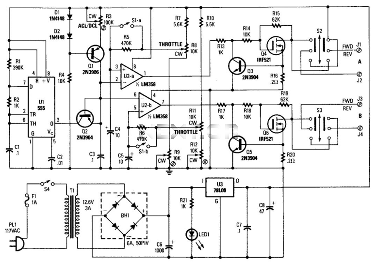
Model Train And Slot-Car Controller
A 555 timer (U1) is configured as an astable multivibrator (oscillator) with a duty cycle of 400:1 and a frequency of 40 Hz. When power is applied to the circuit, capacitor C1 (connected to pin 6 of U1) is discharged,...
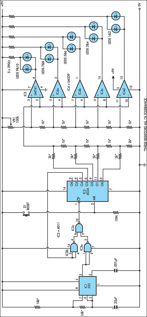
Grand Prix Starting Lights
This circuit replicates the starting light sequence used by FISA in Formula One racing. It can be utilized with slot car sets (such as HO scale AFX, Life Like, or Tyco sets) or radio-controlled cars. The circuit employs a 555...
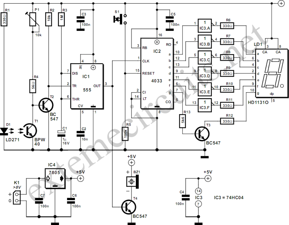
Light Gate With Counter Using 555 And 4033
The circuit described here counts the number of times an infrared beam is interrupted. It can be utilized to count the number of individuals entering a room or to track how often an object, such as a ball, passes through...
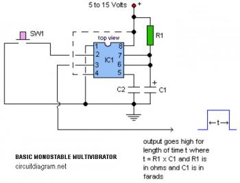
555 IC For Basic Monostable Multivibrator
The following circuit illustrates a basic monostable multivibrator, which is based on the 555 Timer IC. Key features include pin 4 functioning as the RESET pin, with the time period defined by the equation t = R1 x C1.
The basic...
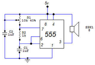
Tone generator with 555
This circuit is based around the 555 timer circuit, used as an astable (free running) oscillator. The frequency (pitch) of the tone is set by the resistors and capacitors in the left side of the circuit. The first one is...