


cmos 4047 power inverter 12vdc
#CMOS 4047
#power inverter
#12V DC
#220V AC
#astable multivibrator
#Darlington transistors
#transformer
#rectangular signal
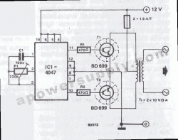
Description: This converter features a central component, the CMOS 4047, which converts a 12V DC voltage into a 220V AC voltage. The 4047 operates as an astable multivibrator. At pins 10 and 11, a symmetrical rectangular signal is generated, which is then amplified by two Darlington transistors, T1 and T2, before reaching the secondary coil of a transformer network rated at 2 x 10V/60VA. The primary coil terminals output a 220V alternating voltage. For improved performance, it is recommended to use a toroidal core transformer to minimize losses. The output frequency can be adjusted within certain limits (50 to 400Hz) using potentiometer P1.
The circuit utilizes the CMOS 4047 as the primary oscillator, which is configured in astable mode to generate a continuous square wave output. This output is characterized by its symmetrical nature, providing a consistent frequency that is essential for the AC conversion process. The generated signal at pins 10 and 11 is critical, as it drives the subsequent amplification stage.
The Darlington pair configuration of transistors T1 and T2 enhances the output current capability, enabling the circuit to effectively drive the transformer. The choice of a transformer with a toroidal core is significant, as it offers advantages such as reduced electromagnetic interference and lower core losses compared to traditional laminated transformers. This choice contributes to the overall efficiency of the converter.
The transformer steps up the 12V input to a 220V output, suitable for powering standard AC devices. The secondary winding is designed to handle the required voltage and current ratings, ensuring safe operation. The inclusion of potentiometer P1 allows for fine-tuning of the output frequency, which can be adjusted between 50Hz and 400Hz. This feature is particularly useful for applications that require specific frequency outputs, such as in variable speed drives or other AC applications.
Overall, the design emphasizes efficiency and flexibility, making it a versatile solution for converting DC voltage to AC voltage while maintaining control over the output frequency.This converter has a central component, the CMOS 4047, and converts a 12V DC voltage to 220V AC voltage. 4047 is utilised as a astable multivibrator. At pin 10 and 11 we find a rectangular symmetrically signal which is amplified by tow Darlington transistors T1 and T2 and finally reaches the secondary coil of a transformer network (2 x 10V/60VA).
Primary coil terminals voltage is 220 alternative voltage. To obtain a better performance use a toroidal core transformer with reduced losses. With P1 the output frequency can be regulated between certain limits (50 400Hz). Disclaimer All files are found using legitimate search engine techniques. This site does not and will not condone hacking into sites to create the links it list. We will and do assume that all links found on the search engines we use are obtained in a legal manner and the webmasters are aware of the links listed on the search engines. If you find a URL that belongs to you, and you did not realize that it was "open to the public", please use the report button to notify the blogmaster of your request to remove it or it will remove within 24 hours.
This is not an invitation for webblog haters to spam with requests to remove content they feel that is objectionable and or unacceptable. Proof of URL ownership is required. NOTICE: This Blog Has Already Been Reviewed And Accepted By Blogger. com
The circuit utilizes the CMOS 4047 as the primary oscillator, which is configured in astable mode to generate a continuous square wave output. This output is characterized by its symmetrical nature, providing a consistent frequency that is essential for the AC conversion process. The generated signal at pins 10 and 11 is critical, as it drives the subsequent amplification stage.
The Darlington pair configuration of transistors T1 and T2 enhances the output current capability, enabling the circuit to effectively drive the transformer. The choice of a transformer with a toroidal core is significant, as it offers advantages such as reduced electromagnetic interference and lower core losses compared to traditional laminated transformers. This choice contributes to the overall efficiency of the converter.
The transformer steps up the 12V input to a 220V output, suitable for powering standard AC devices. The secondary winding is designed to handle the required voltage and current ratings, ensuring safe operation. The inclusion of potentiometer P1 allows for fine-tuning of the output frequency, which can be adjusted between 50Hz and 400Hz. This feature is particularly useful for applications that require specific frequency outputs, such as in variable speed drives or other AC applications.
Overall, the design emphasizes efficiency and flexibility, making it a versatile solution for converting DC voltage to AC voltage while maintaining control over the output frequency.This converter has a central component, the CMOS 4047, and converts a 12V DC voltage to 220V AC voltage. 4047 is utilised as a astable multivibrator. At pin 10 and 11 we find a rectangular symmetrically signal which is amplified by tow Darlington transistors T1 and T2 and finally reaches the secondary coil of a transformer network (2 x 10V/60VA).
Primary coil terminals voltage is 220 alternative voltage. To obtain a better performance use a toroidal core transformer with reduced losses. With P1 the output frequency can be regulated between certain limits (50 400Hz). Disclaimer All files are found using legitimate search engine techniques. This site does not and will not condone hacking into sites to create the links it list. We will and do assume that all links found on the search engines we use are obtained in a legal manner and the webmasters are aware of the links listed on the search engines. If you find a URL that belongs to you, and you did not realize that it was "open to the public", please use the report button to notify the blogmaster of your request to remove it or it will remove within 24 hours.
This is not an invitation for webblog haters to spam with requests to remove content they feel that is objectionable and or unacceptable. Proof of URL ownership is required. NOTICE: This Blog Has Already Been Reviewed And Accepted By Blogger. com
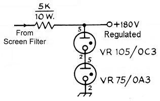
Power Supply Schematic
The power transformer features three secondary windings: 720V at 120mA center-tapped for the plate and screen supplies, 6.3V at 3.5A for the tube filament and bias power supply, and 5V at 3A (unused). Since the 5V secondary is not utilized,...
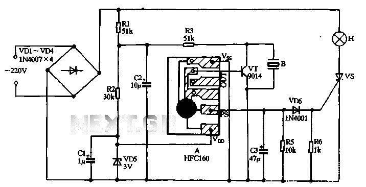
HFC lantern making music controller circuit
220V AC power is supplied through a VD1 to VD4 bridge rectifier and a voltage regulator circuit involving R1, R2, and VD5 components. The output provides a DC voltage of approximately 3V, which powers the manifold A. The manifold generates...
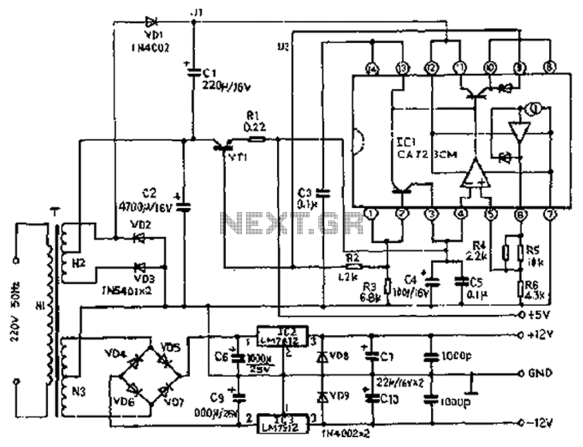
Precision tandem type power supply circuit diagram
The circuit depicted features a secondary N3 center tap transformer (T) with a common point connecting diodes VD2 and VD3 to positive electrodes, along with capacitors C2, C6, C7, and negative electrodes connected to capacitors C9 and C10. Additional components...
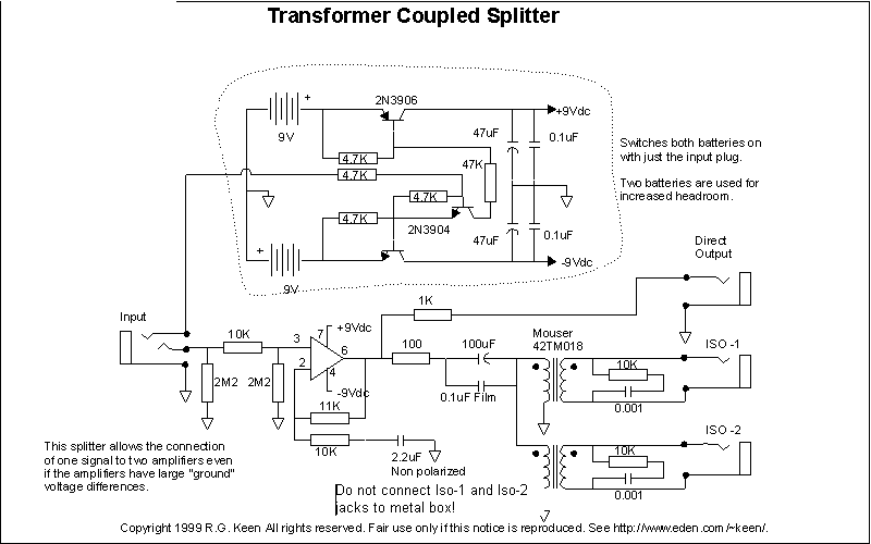
AC to AC Power Supplies and Transformer Circuits
An active amplified transformer isolated signal splitter that enables a hum-free connection of one guitar to multiple amplifiers, while also providing a direct output. This includes a discussion on using audio transformers for equipment interconnections and mentions line-level transformers in...
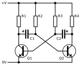
Astable Multivibrator Calculations
For the time it takes to charge to 0.6V, the other capacitor has already charged significantly (a value that cannot be determined because the setup does not function until one of the two states—Q1 is on or Q2 is on—is...
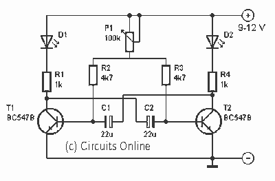
Astable multivibrator with two LED
This is one of the basic circuitry of the electronics. The multivibrator astable shows two LEDs alternately light up with an adjustable speed. The circuit uses two transistors conduct alternately by the capacitors charged and discharged. The rate at which...
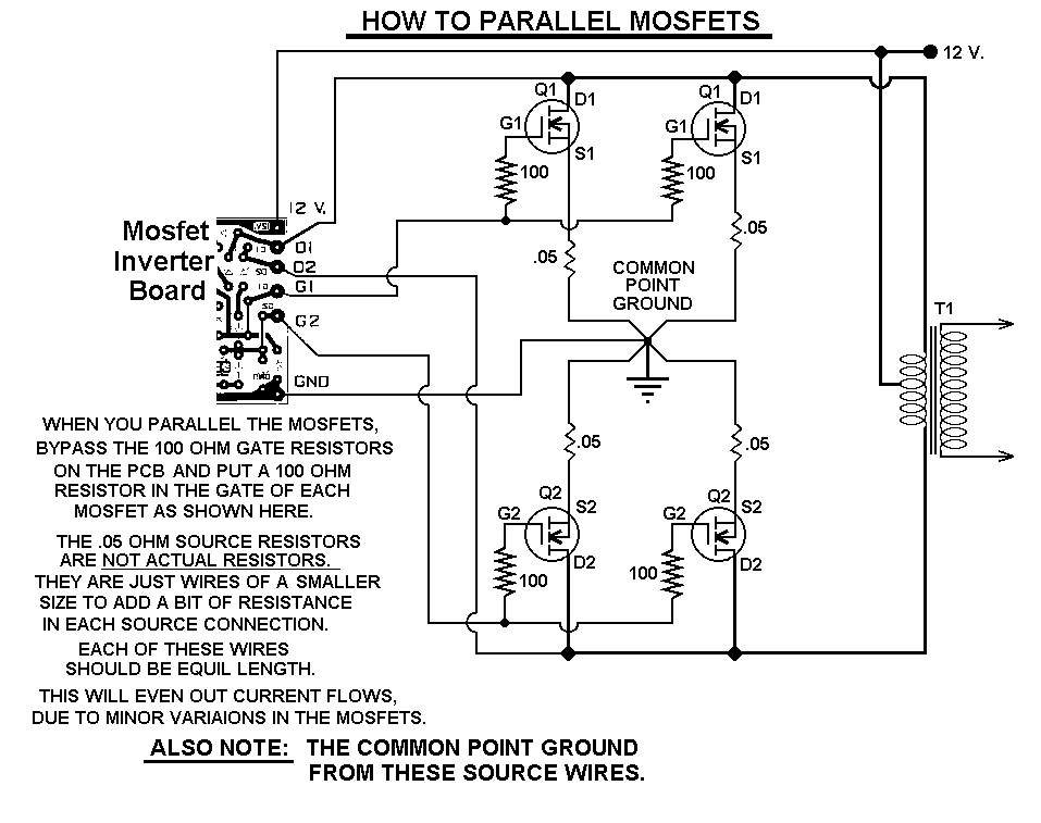
1000 watt power inverter schematic
This 1000-watt power inverter circuit diagram utilizes the MOSFET RF50N06. To achieve higher power output, additional MOSFETs can be connected in parallel with the RF50N06. These MOSFETs are rated for 60 volts and 50 amps. It is essential to include...
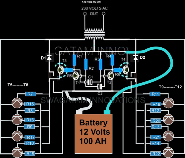
How to Make a Simple 200 VA Homemade Power Inverter Circuit Square Wave Concept
The current design of a power inverter offers an efficiency of approximately 85% and a power output exceeding 200 watts. This document provides a complete circuit schematic and detailed building procedure for a home-built power inverter. While numerous articles on...
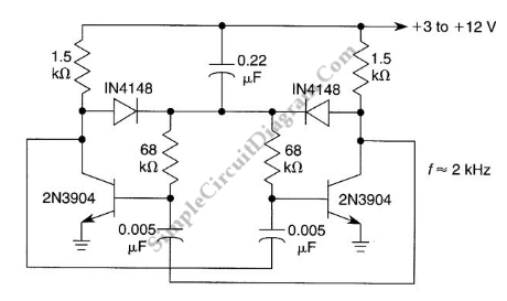
Starting Network for Astable Multivibrator
An astable multivibrator is a flip-flop that produces two unstable states (high and low), functioning as an oscillator.
An astable multivibrator is a fundamental electronic circuit that continuously switches between its two states without requiring any external triggering signals. This...