


making 25w low power inverter circuit
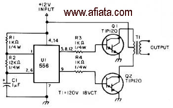
Description: The first section of the 555 timer is configured as an astable oscillator, with R2 and C1 determining the frequency. The output is accessible at pin 5. The second section functions as a phase inverter, with its output available at pin 9. Resistors R3 and R4 prevent output transistors Q1 and Q2 from loading the oscillator.
The 555 timer is a versatile integrated circuit widely used in timer, pulse generation, and oscillator applications. In the astable mode, the timer continuously switches between high and low states, generating a square wave output. The frequency of oscillation is determined by the values of resistors R2 and capacitor C1, which set the charge and discharge times of the timing capacitor.
The output from the astable oscillator is taken from pin 5, which provides a square wave signal. This output can drive other components or circuits directly, depending on the load requirements. The second section of the 555 timer acts as a phase inverter, which is crucial for applications requiring signal inversion or phase shifting. The output from this section is available at pin 9, allowing for further signal manipulation or interfacing with other circuit elements.
Resistors R3 and R4 play an essential role in maintaining the stability of the circuit. They are connected to the outputs of transistors Q1 and Q2, ensuring that these outputs do not excessively load the oscillator. This configuration helps maintain the integrity of the oscillation frequency while preventing distortion that could arise from improper loading conditions.
In summary, this configuration of the 555 timer as an astable oscillator with a phase inverter provides a reliable means of generating and manipulating pulse signals. The careful selection of component values and the inclusion of load-resisting elements ensure robust performance across various electronic applications.The first section of the 555 timer is wires as an astable oscillator with R2 and C1 setting the frequency. The output is available at pin 5. The second section is wired as a phase inverter. That output is available at pin 9. Resistor R3 and R4 keep output transistor Q1 and Q2 from loading down the oscillator.
The 555 timer is a versatile integrated circuit widely used in timer, pulse generation, and oscillator applications. In the astable mode, the timer continuously switches between high and low states, generating a square wave output. The frequency of oscillation is determined by the values of resistors R2 and capacitor C1, which set the charge and discharge times of the timing capacitor.
The output from the astable oscillator is taken from pin 5, which provides a square wave signal. This output can drive other components or circuits directly, depending on the load requirements. The second section of the 555 timer acts as a phase inverter, which is crucial for applications requiring signal inversion or phase shifting. The output from this section is available at pin 9, allowing for further signal manipulation or interfacing with other circuit elements.
Resistors R3 and R4 play an essential role in maintaining the stability of the circuit. They are connected to the outputs of transistors Q1 and Q2, ensuring that these outputs do not excessively load the oscillator. This configuration helps maintain the integrity of the oscillation frequency while preventing distortion that could arise from improper loading conditions.
In summary, this configuration of the 555 timer as an astable oscillator with a phase inverter provides a reliable means of generating and manipulating pulse signals. The careful selection of component values and the inclusion of load-resisting elements ensure robust performance across various electronic applications.The first section of the 555 timer is wires as an astable oscillator with R2 and C1 setting the frequency. The output is available at pin 5. The second section is wired as a phase inverter. That output is available at pin 9. Resistor R3 and R4 keep output transistor Q1 and Q2 from loading down the oscillator.
Transistor Circuits
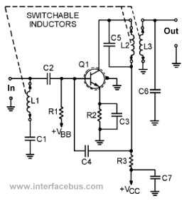
This page presents several transistor circuits that are not commonly found on other pages due to the absence of a specific topic. These circuits, however, illustrate particular points but lack detailed descriptions. An example of an RF amplifier circuit using...
Miniature Beeping Circuit
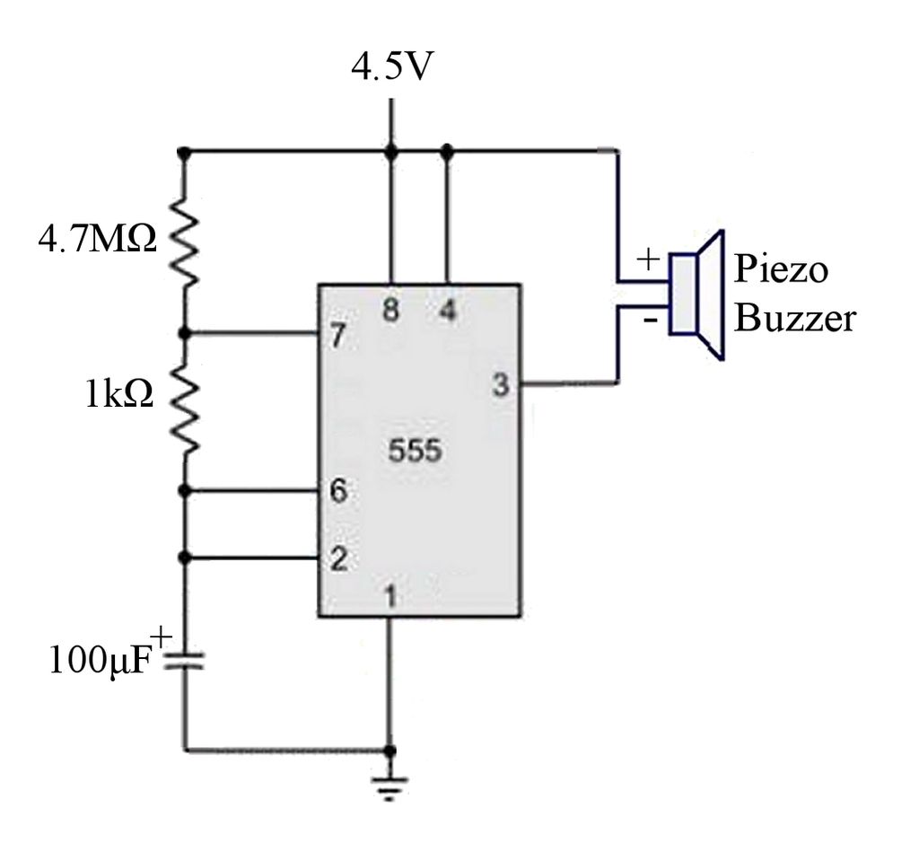
The circuit is a basic 555 timer circuit in astable mode. In this configuration, the integrated circuit (IC) generates a brief pulse to the buzzer at regular intervals.
The 555 timer in astable mode operates as an oscillator, producing a continuous...
Transistor act as a switch
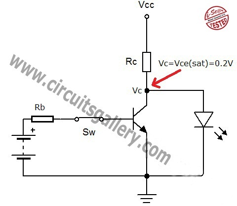
A transistor is a semiconductor device utilized for switching and amplifying weak signals. This article details the operation of a transistor and its function as a switch. Currently, transistors are integrated into most electronic equipment for switching applications, with digital...
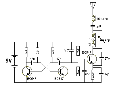
100 transistor circuits
A straightforward method to create a speaker transformer involves winding turns around a ferrite rod. The primary winding consists of 300 turns of 0.01mm wire, which is very fine, wound over the secondary and concluding with a loop of wire...
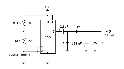
9V to 5V converter schematic with 555
A 555 timer can be used to generate a square wave to produce a negative voltage relative to the negative battery terminal. When the timer output at pin 3 goes positive, the series 22 uF capacitor charges through the diode...
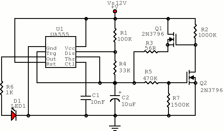
555 Pulse generator
The first positive pulse from a classic 555-based oscillator is always 1.6 times longer than the subsequent pulses. This discrepancy occurs because, during the initial cycle, capacitor C2 begins charging from 0 V. While this is typically not an issue,...

Transistor Ignition
This transistor ignition circuit enhances vehicle starting and ensures smoother engine operation, especially at both high and low RPMs. It contributes to lower fuel consumption, reduced emissions, and decreased maintenance costs. The system promotes economical and electronic driving.
The transistor ignition...
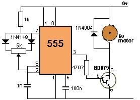
dc motor control using 555 timer circuit
This project utilizes a 555 timer to control the speed of a 6-volt DC motor. Speed adjustment is achieved by rotating a 50 kΩ potentiometer either to the left or right.
The circuit employs a 555 timer configured in astable mode...
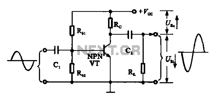
Common emitter amplifier works a
A common emitter amplifier functions as a signal amplification unit by utilizing a common emitter configuration, which inverts the output signal. This operation can be analyzed by observing the input signal waveform. During the first quarter of the period, the...