


220 V flashing light
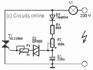
Description: Here a simple design for a flashlight that operates on 220 V. The circuit is constructed with a triac. By R1 and C1 P1 is charged. Charging time is adjustable with P2. When C1 is charged, turn the diac D2. C1 onlaadt than through T1. The lamp lights up. If the voltage on C1 is too low, the diac does not conduct and the capacitor can recharge. With P1, the flashing frequency are regulated. P2 is the gate current, carried at the time of the lamp affects. More: Parts List R1 = 6.8 kOhm W ½ P1 = 1 kOhm P2 = 100 kOhm C1 = 220 V ?F/40 D1 = 1N4004 Diac D2 = ER 900 T1 = triac TIC216M L1 = 220 V max 500 W
This circuit design outlines a simple flashlight system that operates on a 220 V AC supply. The primary component is a triac (T1), specifically the TIC216M, which is utilized for controlling the power delivered to the lamp (L1) rated for a maximum of 500 W. The circuit employs a capacitive charging mechanism to regulate the operation of the flashlight.
The resistor R1, valued at 6.8 kOhm, and capacitor C1 (220 V rated) form an RC charging circuit that allows for the gradual charging of C1 when the circuit is powered. The adjustment of the charging time is facilitated by the potentiometer P2 (100 kOhm), which allows for fine-tuning of the charge time, thereby controlling the duration before the lamp is activated.
Once C1 reaches a predetermined voltage threshold, it triggers the diac D2 (ER 900), which in turn allows current to flow through the triac T1. The activation of T1 subsequently energizes the lamp L1, causing it to illuminate. If the voltage across C1 falls below the required level, the diac will not conduct, allowing the capacitor to recharge without triggering the lamp, thus preventing unwanted flashing.
Additionally, the potentiometer P1 (1 kOhm) is used to adjust the flashing frequency of the lamp. By modifying the resistance, the time constant of the RC circuit is altered, leading to variations in how quickly C1 charges and discharges, effectively controlling the on-off cycling of the lamp.
The diode D1 (1N4004) serves as a protective component, preventing reverse polarity or voltage spikes from damaging the circuit components. This circuit design is suitable for applications where a simple and adjustable flashing flashlight is required, leveraging basic electronic components for functionality.Here a simple design for a flashlight that operates on 220 V. The circuit is constructed with a triac. By R1 and C1 P1 is charged. Charging time is adjustable with P2. When C1 is charged, turn the diac D2. C1 onlaadt than through T1. The lamp lights up. If the voltage on C1 is too low, the diac does not conduct and the capacitor can recharge. With P1, the flashing frequency are regulated. P2 is the gate current, carried at the time of the lamp affects. Parts List R1 = 6.8 kOhm W ½ P1 = 1 kOhm P2 = 100 kOhm C1 = 220 V ?F/40 D1 = 1N4004 Diac D2 = ER 900 T1 = triac TIC216M L1 = 220 V max 500 W
This circuit design outlines a simple flashlight system that operates on a 220 V AC supply. The primary component is a triac (T1), specifically the TIC216M, which is utilized for controlling the power delivered to the lamp (L1) rated for a maximum of 500 W. The circuit employs a capacitive charging mechanism to regulate the operation of the flashlight.
The resistor R1, valued at 6.8 kOhm, and capacitor C1 (220 V rated) form an RC charging circuit that allows for the gradual charging of C1 when the circuit is powered. The adjustment of the charging time is facilitated by the potentiometer P2 (100 kOhm), which allows for fine-tuning of the charge time, thereby controlling the duration before the lamp is activated.
Once C1 reaches a predetermined voltage threshold, it triggers the diac D2 (ER 900), which in turn allows current to flow through the triac T1. The activation of T1 subsequently energizes the lamp L1, causing it to illuminate. If the voltage across C1 falls below the required level, the diac will not conduct, allowing the capacitor to recharge without triggering the lamp, thus preventing unwanted flashing.
Additionally, the potentiometer P1 (1 kOhm) is used to adjust the flashing frequency of the lamp. By modifying the resistance, the time constant of the RC circuit is altered, leading to variations in how quickly C1 charges and discharges, effectively controlling the on-off cycling of the lamp.
The diode D1 (1N4004) serves as a protective component, preventing reverse polarity or voltage spikes from damaging the circuit components. This circuit design is suitable for applications where a simple and adjustable flashing flashlight is required, leveraging basic electronic components for functionality.Here a simple design for a flashlight that operates on 220 V. The circuit is constructed with a triac. By R1 and C1 P1 is charged. Charging time is adjustable with P2. When C1 is charged, turn the diac D2. C1 onlaadt than through T1. The lamp lights up. If the voltage on C1 is too low, the diac does not conduct and the capacitor can recharge. With P1, the flashing frequency are regulated. P2 is the gate current, carried at the time of the lamp affects. Parts List R1 = 6.8 kOhm W ½ P1 = 1 kOhm P2 = 100 kOhm C1 = 220 V ?F/40 D1 = 1N4004 Diac D2 = ER 900 T1 = triac TIC216M L1 = 220 V max 500 W
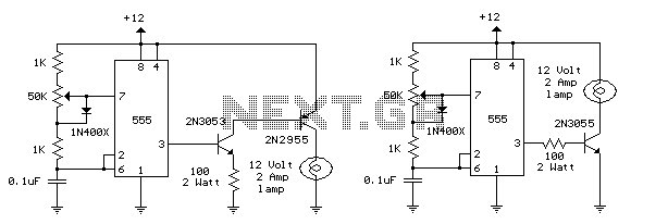
TRIAC Light Dimmer Circuit
This circuit is designed to dim lights with a maximum capacity of approximately 350 watts. It employs a standard TRIAC circuit configuration, which has been observed to generate minimal heat during operation. It is important to note that this circuit...
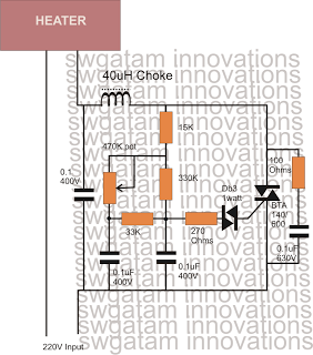
How to Make a 25 Amp 1500 watts Heater Controller Circuit
Controlling heaters rated up to 1500 watts requires stringent specifications for the controlling unit to ensure safe and effective operation. The introduction of advanced snubber-less Triacs and Diacs has made it relatively easier to implement heater controllers at high wattage...
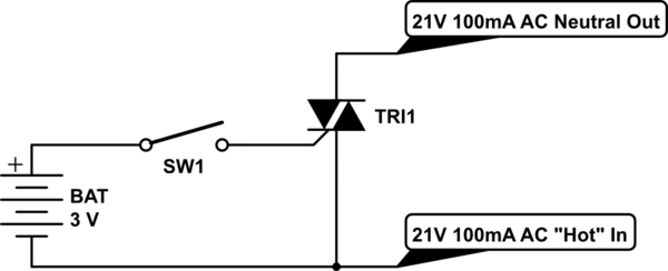
Mixing AC and DC power in a circuit
Control a furnace using a 3.3V microcontroller. The furnace operates by connecting a common 21V AC "hot" line to one of two AC "neutral" output lines: Fan and Heat. When connected, they have relatively low current flow, approximately 100mA. A...
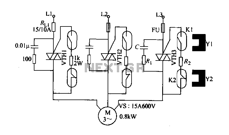
Cloth from idling stop saving circuit
The circuit diagram illustrates a female textile machine power control circuit. VTH1-VTH3 represent TRIACs, while R and C form the absorption line. Rz serves as the triggering current limiting resistor. K1 is designated for starting the reed, and K2 is...
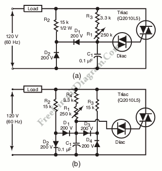
Diac-Triac Phase/Power Control without Hysteresis
Hysteresis in a lamp dimmer or other electrical appliances may cause issues when fine-tuning, leading to a feeling of being out of control. This is a circuit of.
Hysteresis in dimmer circuits can lead to undesirable fluctuations in brightness levels, particularly...

Triac mains light dimmer
This is the schematic of the conventional light dimmer. L1 and C2, C3 form the lichtnetontstoring. In this circuit meets almost every TRIAC as a TIC226D. For C1, C2 and C3 good capacitors (MKT example) with a minimum operating voltage...
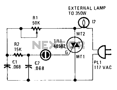
Triac lamp dimmer
A heatsink allows the TRIAC (TR1) to manage a maximum power of 350 watts. The neon lamp, II, will not activate the gate until the TRIAC begins conducting, and resistor R1 can be adjusted to set the desired lighting level.
The...
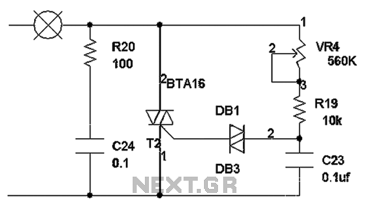
Triac dimming circuit diagram
The TRIAC dimmer circuit diagram operates on the principle that a 220V lamp is controlled through the charging of capacitor C23 via resistors VR4 and R19. The charging time is influenced by the values of VR4 and R19, where a...
capacitor Choosing components for a triacs snubber
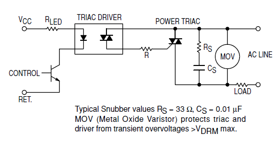
Interfacing the BT139-600 TRIAC with the MOC3051-M Opto-triac requires the construction of a snubber circuit as illustrated in the MOC3051M opto-triac's datasheet on page 8, figure 12. The load connected to this circuit will be a 230V AC, 4A motor....