


Diac-Triac Phase/Power Control without Hysteresis
#diac
#triac
#phase control
#power control
#lamp dimmer
#hysteresis
#fine tuning
#electric appliance
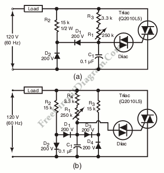
Description: Hysteresis in a lamp dimmer or other electrical appliances may cause issues when fine-tuning, leading to a feeling of being out of control. This is a circuit of.
Hysteresis in dimmer circuits can lead to undesirable fluctuations in brightness levels, particularly in applications requiring precise control. The circuit typically employs a feedback mechanism that stabilizes the output against small variations in input voltage or load conditions.
In a standard lamp dimmer circuit, the hysteresis effect is often introduced by components such as operational amplifiers or comparators, which help to define a threshold level for switching the output state. This threshold creates a zone of operation where small changes in input do not affect the output state, thereby preventing rapid on-off cycling, which can be perceived as flickering.
To design a more reliable dimmer circuit with minimal hysteresis, a careful selection of resistor and capacitor values is essential. The feedback loop should be configured to ensure that the operational amplifier or comparator responds only to significant changes in input, thus avoiding unnecessary adjustments in output.
For example, in a typical dimmer circuit, a variable resistor (potentiometer) can be used to adjust the reference voltage at the inverting input of the comparator. The non-inverting input receives the feedback voltage from the output, which is influenced by the load current. The output of the comparator drives a power transistor or a TRIAC, controlling the AC voltage applied to the lamp.
To further enhance fine-tuning capabilities, additional circuitry such as a low-pass filter can be incorporated to smooth out rapid fluctuations in the input signal. This will help to maintain a stable dimming effect, allowing for more precise adjustments without the adverse effects of hysteresis.
In summary, addressing hysteresis in lamp dimmers involves a thoughtful approach to circuit design, focusing on feedback mechanisms and component selection to achieve stable and controllable brightness levels.Hysteresis in lamp dimmer or in other electric appliance might cause some trouble if you need a fine tuning, something like out of control. This is a circuit of.
Hysteresis in dimmer circuits can lead to undesirable fluctuations in brightness levels, particularly in applications requiring precise control. The circuit typically employs a feedback mechanism that stabilizes the output against small variations in input voltage or load conditions.
In a standard lamp dimmer circuit, the hysteresis effect is often introduced by components such as operational amplifiers or comparators, which help to define a threshold level for switching the output state. This threshold creates a zone of operation where small changes in input do not affect the output state, thereby preventing rapid on-off cycling, which can be perceived as flickering.
To design a more reliable dimmer circuit with minimal hysteresis, a careful selection of resistor and capacitor values is essential. The feedback loop should be configured to ensure that the operational amplifier or comparator responds only to significant changes in input, thus avoiding unnecessary adjustments in output.
For example, in a typical dimmer circuit, a variable resistor (potentiometer) can be used to adjust the reference voltage at the inverting input of the comparator. The non-inverting input receives the feedback voltage from the output, which is influenced by the load current. The output of the comparator drives a power transistor or a TRIAC, controlling the AC voltage applied to the lamp.
To further enhance fine-tuning capabilities, additional circuitry such as a low-pass filter can be incorporated to smooth out rapid fluctuations in the input signal. This will help to maintain a stable dimming effect, allowing for more precise adjustments without the adverse effects of hysteresis.
In summary, addressing hysteresis in lamp dimmers involves a thoughtful approach to circuit design, focusing on feedback mechanisms and component selection to achieve stable and controllable brightness levels.Hysteresis in lamp dimmer or in other electric appliance might cause some trouble if you need a fine tuning, something like out of control. This is a circuit of.
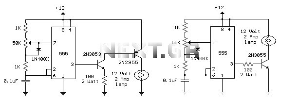
TRIAC Light Dimmer Circuit
This circuit is designed to dim lights with a maximum capacity of approximately 350 watts. It employs a standard TRIAC circuit configuration, which has been observed to generate minimal heat during operation. It is important to note that this circuit...
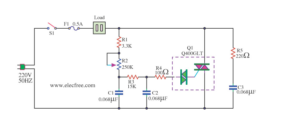
1200 Watt AC Dimmer by Triac Q4006LT
This is a 1200-watt AC power dimmer that utilizes a triac Q4006LT.
The 1200-watt AC power dimmer circuit is designed to control the brightness of incandescent lamps and other resistive loads. The core component, the triac Q4006LT, is a semiconductor device...
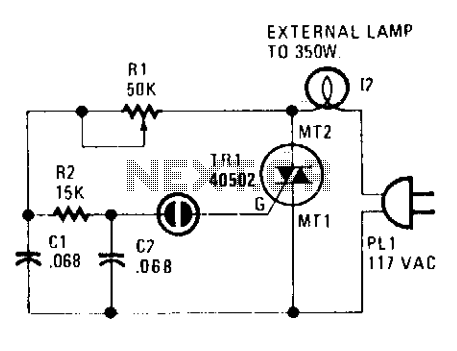
Triac lamp dimmer
A heatsink allows the TRIAC (TR1) to manage a maximum power of 350 watts. The neon lamp, II, will not activate the gate until the TRIAC begins conducting, and resistor R1 can be adjusted to set the desired lighting level.
The...
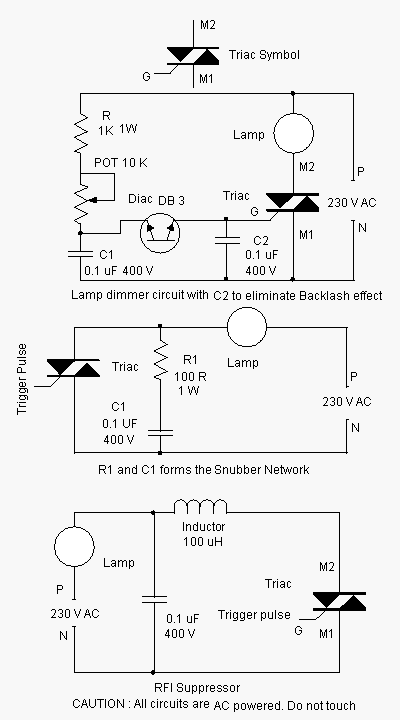
Triac Optimization Circuits Schematic Diagram
Advanced power control systems utilize electronic components such as thyristors for power switching, motor control, and other applications. These systems are involved in inverter design, lamp dimming, and speed control of motors. Triacs are the most commonly used semiconductor devices...
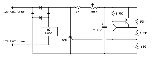
Lamp Dimmer schematic
The full wave phase control circuit below was found in a RCA power circuits book from 1969. The load is placed in series with the AC line and the four diodes provide a full wave rectified voltage to the anode...

Triac low output problem
The circuit consists of two separate 3023 optoisolators controlling two distinct triacs, each responsible for powering a large 3-phase contactor. One contactor operates correctly, while the other experiences issues, not receiving sufficient power to engage fully. The upper image illustrates...
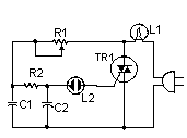
simple TRIAC Light Dimmer
This little circuit can be used to dim lights up to about 350 watts. It uses a simple, standard TRIAC circuit that, in my experience, generates very little heat. Please note that this circuit cannot be used with fluorescent lights....
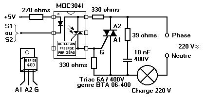
switching ac loads triac
A circuit is needed to control a couple of large AC solenoid valves and several single-phase AC motors. The line voltage is 132VAC, with the solenoids drawing 1A and the motors drawing 13A and 27A when operating. The goal is...
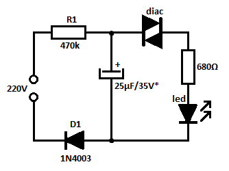
diac controlled led flasher 3
This is likely the simplest concept for generating a flashing light from an LED using alternating current (AC). The circuit provides a straightforward method for flashing one or more LEDs using high-voltage direct current (DC) sourced from mains electricity. It...