


BA5173 HT7706 dimming control ASIC
#dimming control
#ASIC
#voltage rectifier
#DC voltage
#zero-crossing
#resistance voltage
#half-wave rectifier
#5V supply
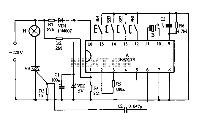
Description: The circuit consists of components VDI, VD2, R1, and C1, which together form a resistance voltage half-wave rectifier circuit. This configuration produces a DC output voltage of 5V to supply various devices. R2 is utilized to provide an AC zero-crossing signal for the manifold. R5 serves as the external oscillator resistor for the manifold. R6 and C3 work together to ensure the integration task is performed effectively, achieving a clear reset for each power block. Switches SB1 to SB4 facilitate stepless dimming, four-step dimming, off-delay, and automatic cycling light control, allowing users to select one or multiple keys based on their preferences.
The circuit described is a half-wave rectifier configuration designed to convert alternating current (AC) into direct current (DC), specifically targeting a 5V output suitable for powering various electronic devices. The use of diodes VDI and VD2 ensures that only one half of the AC waveform is utilized, effectively rectifying the input signal.
Resistor R1 plays a crucial role in limiting the current through the circuit, thereby protecting the diodes from excessive current that could lead to damage. The capacitor C1 serves to smooth out the rectified output, reducing voltage ripple and providing a more stable DC voltage to the load.
Resistor R2 is critical in generating an AC zero-crossing signal, which can be used for synchronization purposes in applications where precise timing is necessary. This feature is particularly useful in systems that require phase control or timing adjustments.
R5, as the external oscillator resistor, is essential for generating the required frequency for the manifold's operation. This resistor helps to establish the oscillation characteristics, ensuring that the manifold operates efficiently within its intended parameters.
The combination of R6 and capacitor C3 is employed to manage the timing and reset functions of the power blocks. This integration is vital for maintaining the operational integrity of the circuit, ensuring that each power block can reset and initialize correctly after each cycle.
The circuit includes a user interface through switches SB1 to SB4, which provide various dimming options and operational modes. These switches allow for stepless dimming, enabling users to adjust brightness smoothly, while the four-step dimming feature provides preset levels of brightness for convenience. The off-delay function allows users to set a timer for the light to turn off after a specified duration, and the automatic cycling feature enables the light to operate in a repeating on-off cycle, enhancing usability in different scenarios.
Overall, this circuit design offers flexibility and control for managing lighting and power supply applications, making it suitable for various electronic projects.FIG VDI, VD2, Rl and Cl form resistance voltage half-wave rectifier circuit, the output DC voltage 5v supply manifold with electricity. R2 for the manifold provides AC zero-cro ssing signal. R5 is manifold external oscillator resistor. R6 and C3 to ensure the integration task to achieve clear reset each power block. SB1 ~ SB4 are the stepless dimming, four stepper dimming, off delay and automatic cycle switch light touch of a button, readers can choose one or four keys are used according to their needs any.
The circuit described is a half-wave rectifier configuration designed to convert alternating current (AC) into direct current (DC), specifically targeting a 5V output suitable for powering various electronic devices. The use of diodes VDI and VD2 ensures that only one half of the AC waveform is utilized, effectively rectifying the input signal.
Resistor R1 plays a crucial role in limiting the current through the circuit, thereby protecting the diodes from excessive current that could lead to damage. The capacitor C1 serves to smooth out the rectified output, reducing voltage ripple and providing a more stable DC voltage to the load.
Resistor R2 is critical in generating an AC zero-crossing signal, which can be used for synchronization purposes in applications where precise timing is necessary. This feature is particularly useful in systems that require phase control or timing adjustments.
R5, as the external oscillator resistor, is essential for generating the required frequency for the manifold's operation. This resistor helps to establish the oscillation characteristics, ensuring that the manifold operates efficiently within its intended parameters.
The combination of R6 and capacitor C3 is employed to manage the timing and reset functions of the power blocks. This integration is vital for maintaining the operational integrity of the circuit, ensuring that each power block can reset and initialize correctly after each cycle.
The circuit includes a user interface through switches SB1 to SB4, which provide various dimming options and operational modes. These switches allow for stepless dimming, enabling users to adjust brightness smoothly, while the four-step dimming feature provides preset levels of brightness for convenience. The off-delay function allows users to set a timer for the light to turn off after a specified duration, and the automatic cycling feature enables the light to operate in a repeating on-off cycle, enhancing usability in different scenarios.
Overall, this circuit design offers flexibility and control for managing lighting and power supply applications, making it suitable for various electronic projects.FIG VDI, VD2, Rl and Cl form resistance voltage half-wave rectifier circuit, the output DC voltage 5v supply manifold with electricity. R2 for the manifold provides AC zero-cro ssing signal. R5 is manifold external oscillator resistor. R6 and C3 to ensure the integration task to achieve clear reset each power block. SB1 ~ SB4 are the stepless dimming, four stepper dimming, off delay and automatic cycle switch light touch of a button, readers can choose one or four keys are used according to their needs any.
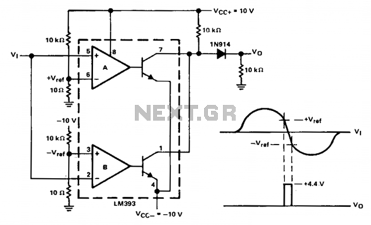
Zero-crossing detector
This zero-crossing detector employs a dual LM393 comparator and allows for easy control of hysteresis through the reference levels set on the comparator inputs. The illustrated circuit is powered by +10 V power supplies, and the input signal can be...
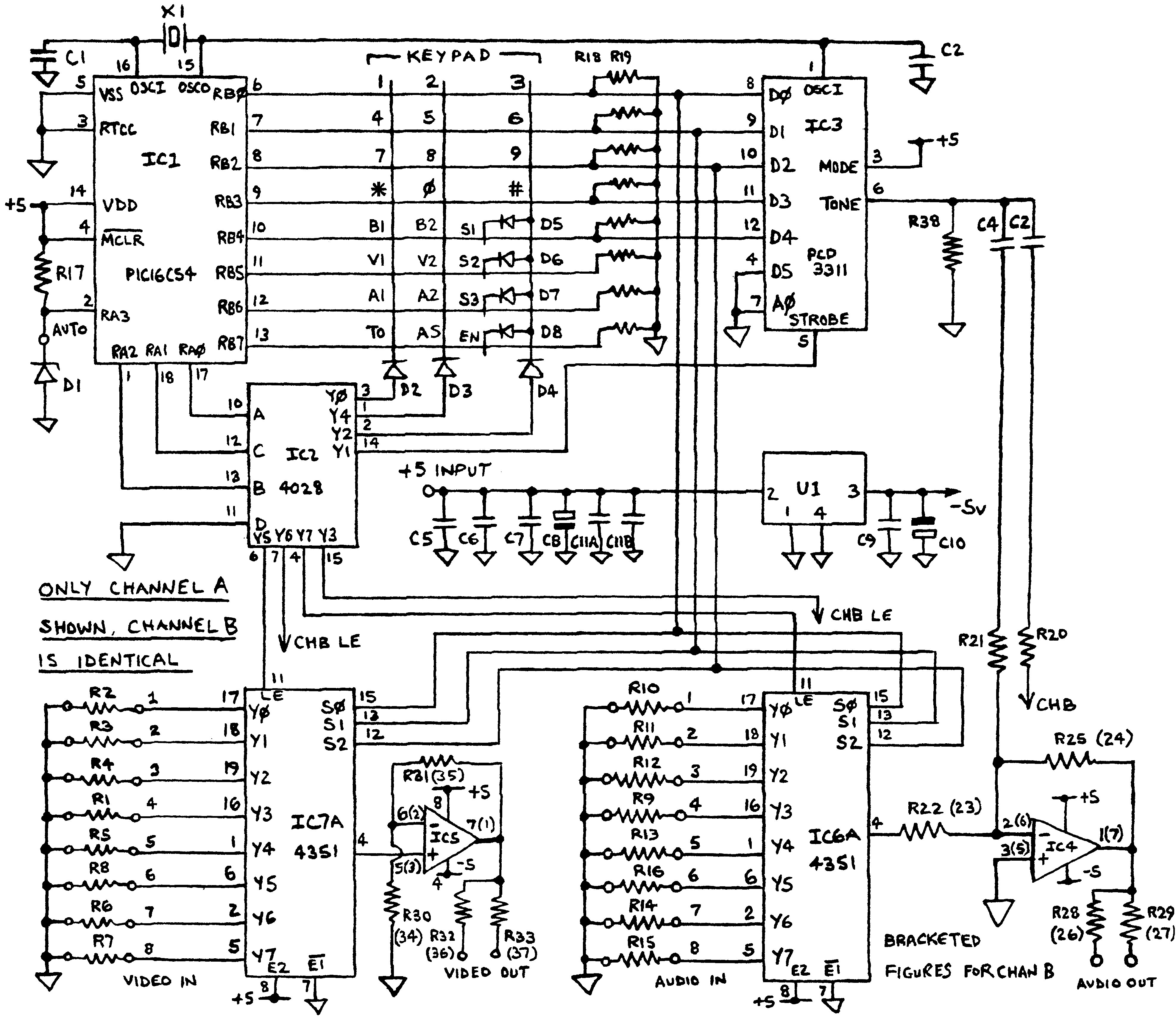
AV Switch circuit
Before applying power, check for shorts on the board. This design operates from a 5V supply; connecting it directly to a 12V supply will certainly damage it. The current draw is minimal, approximately 70mA, so if using a 12V power...
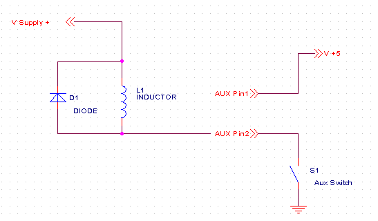
KMotion Connectors
The typical current consumption is 0.7 Amps when no user input/output is connected. Additional current may be necessary depending on the amount of digital input/output and analog +/- 15V consumed by the user. The board generates up to 2 watts...
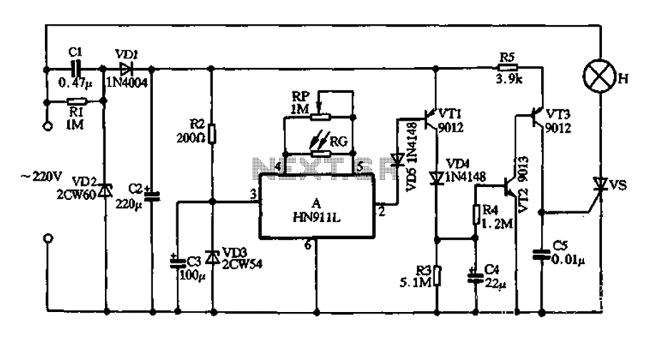
HN911L produced by induction lighting
A simple half-wave rectifier capacitor step-down regulator circuit composed of VD1, VD2, C1, and C2 generates a DC voltage of approximately 12V after power is supplied across capacitor C2. The transistors VT1-VT3 are configured for delay circuits. This DC voltage...
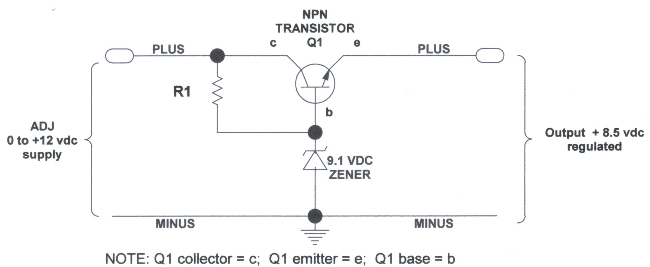
voltage regulators
DC Voltage Regulator (NPN & Zener Regulator) There are instances where it is handy to have a regulated DC voltage power supply for use on your model.
A DC voltage regulator is an essential component in electronic circuits that provides a...
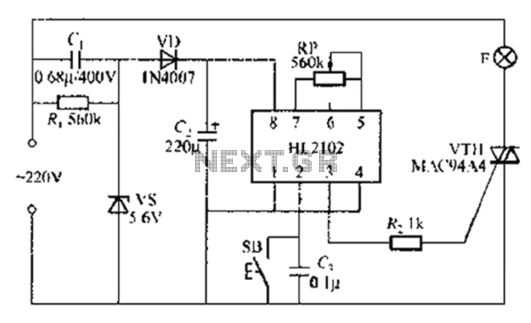
By ASIC delay lamp circuit
A thirty mining lamp control ASIC production delay lamp circuit is straightforward. It utilizes the HL2102 IC from Wuxi Love Core Microelectronics Co., Ltd. The circuit is designed to control a light with a timed delay, allowing for regular intervals...
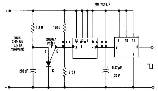
Dc Output Chopper Circuit
A direct current (DC) voltage source within the range of 2 to 15 volts can be converted into a unipolar square wave. This square wave has a peak amplitude that is nearly equal to the DC source voltage, with lightly...