


Backup Lamp Circuit
#backup lamp
#CdS photocell
#NE-2
#power failure
#ambient light
#automatic lighting
#emergency light
#photocell sensor
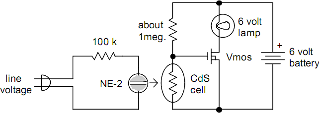
Description: This compact circuit is designed to be cost-effective, particularly useful during instances when the power supply is interrupted, such as while taking a shower. The backup lamp remains off as long as the CdS photocell is exposed to light from either the NE-2 neon bulb or ambient room light. In the event of a power failure at night, the lamp will activate. The 6-volt lamp should be positioned away from the photocell to ensure maximum brightness. The sensitivity can be adjusted by varying the 1-megohm resistor. Most N-channel power FETs, such as the VN-67, will function effectively if they operate well with a 6-volt supply. The NE-2 can be placed directly atop the photocell, ensuring that the leads do not contact other conductors. This design is both safe and portable, although it should be turned off at night when not in use. Alternatively, neon night lights can replace the NE-2, as they have a longer lifespan compared to 7-watt incandescent bulbs, minimizing battery drain. The standby lamp can be housed in an empty jar, with the photocell shielded from the lamp's light. Position the jar near the night light to deactivate the standby lamp in dark conditions. This configuration allows for easy transport, similar to an electronic candle, since the night light is not mechanically connected.
The circuit operates primarily on the principles of light sensing and automatic switching. The CdS photocell acts as a light-dependent resistor, changing its resistance based on the intensity of light it receives. When ambient light or light from the NE-2 bulb is present, the resistance of the photocell is low, preventing the activation of the lamp. However, when darkness falls, the resistance increases, allowing current to flow through the circuit and energizing the lamp.
For optimal performance, the 6-volt lamp must be positioned strategically to avoid directly illuminating the photocell, which could inadvertently keep the lamp off. The adjustable 1-megohm resistor allows for fine-tuning of the photocell's sensitivity, ensuring that the lamp responds appropriately to varying light conditions. The use of an N-channel power FET like the VN-67 is crucial for switching the lamp on and off, as it can handle the required current and voltage levels.
When assembling the circuit, care should be taken to ensure that the NE-2 bulb is securely mounted above the photocell while avoiding any short circuits with the leads. The choice of using a neon night light instead of an incandescent bulb is advantageous due to its durability and lower power consumption, which extends the operational life of the circuit.
The design's portability is enhanced by housing the circuit in an empty jar, which can be easily moved. Shielding the photocell from light emitted by the lamp ensures that the lamp only activates in complete darkness, providing a reliable backup lighting solution. This setup not only serves as a practical emergency light but also offers a unique, transportable lighting option, reminiscent of an electronic candle.This little circuit will pay for itself many times over the first time it is used, especially if you are in the shower. This back-up lamp stays off as long as light falls on the CdS photocell from either the NE-2 or from room ambient light.
So, if the power fails at night, the lamp will light. The 6 volt lamp should be directed away from the photocell to achieve full brightness and the 1 meg. resistor may be varied to adjust the sensitivity. Most N-channel power fets such as the VN-67 will work if they turn on well with 6 volts. The NE-2 may be placed directly on top of the cell but make sure the leads do not touch other conductors.
This design is safe and portable but it must be turned off at night when not in use. Alternately, neon night lights are available which could be used in place of the NE-2. These little round night lights won't burn out like the 7-watt incandescent bulbs which would result in unnecessary battery drain. The standby lamp may be built into an empty jar with the photocell shielded from the lamp. Place the jar close to the night light to turn off the standby lamp when the room is dark. This version may be freely carried away like an electronic candle since the nightlight is not mechanically connected.
The circuit operates primarily on the principles of light sensing and automatic switching. The CdS photocell acts as a light-dependent resistor, changing its resistance based on the intensity of light it receives. When ambient light or light from the NE-2 bulb is present, the resistance of the photocell is low, preventing the activation of the lamp. However, when darkness falls, the resistance increases, allowing current to flow through the circuit and energizing the lamp.
For optimal performance, the 6-volt lamp must be positioned strategically to avoid directly illuminating the photocell, which could inadvertently keep the lamp off. The adjustable 1-megohm resistor allows for fine-tuning of the photocell's sensitivity, ensuring that the lamp responds appropriately to varying light conditions. The use of an N-channel power FET like the VN-67 is crucial for switching the lamp on and off, as it can handle the required current and voltage levels.
When assembling the circuit, care should be taken to ensure that the NE-2 bulb is securely mounted above the photocell while avoiding any short circuits with the leads. The choice of using a neon night light instead of an incandescent bulb is advantageous due to its durability and lower power consumption, which extends the operational life of the circuit.
The design's portability is enhanced by housing the circuit in an empty jar, which can be easily moved. Shielding the photocell from light emitted by the lamp ensures that the lamp only activates in complete darkness, providing a reliable backup lighting solution. This setup not only serves as a practical emergency light but also offers a unique, transportable lighting option, reminiscent of an electronic candle.This little circuit will pay for itself many times over the first time it is used, especially if you are in the shower. This back-up lamp stays off as long as light falls on the CdS photocell from either the NE-2 or from room ambient light.
So, if the power fails at night, the lamp will light. The 6 volt lamp should be directed away from the photocell to achieve full brightness and the 1 meg. resistor may be varied to adjust the sensitivity. Most N-channel power fets such as the VN-67 will work if they turn on well with 6 volts. The NE-2 may be placed directly on top of the cell but make sure the leads do not touch other conductors.
This design is safe and portable but it must be turned off at night when not in use. Alternately, neon night lights are available which could be used in place of the NE-2. These little round night lights won't burn out like the 7-watt incandescent bulbs which would result in unnecessary battery drain. The standby lamp may be built into an empty jar with the photocell shielded from the lamp. Place the jar close to the night light to turn off the standby lamp when the room is dark. This version may be freely carried away like an electronic candle since the nightlight is not mechanically connected.
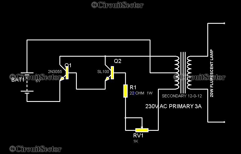
20W Low cost Emergency Light PCB
This is a straightforward circuit for an emergency light that can be assembled with relative ease. The components include two transistors, a transformer, a 20 Watt fluorescent tube, a 6V battery, and several resistors and potentiometers. The transformer in this...
emergency light circuit diagram
The circuit is a battery charging system powered by Q2, Q6, R8, and D10, which provides constant current to charge the battery. When an external power supply is present, the charging current flows through R8 and D10 to charge the...
emergency light circuit diagram
The automatic emergency light circuit has the following features: 1. When the mains supply (230V AC) is available, it charges a 12V battery up to 13.5V, after which the battery is disconnected from the charging section. 2. When the battery...
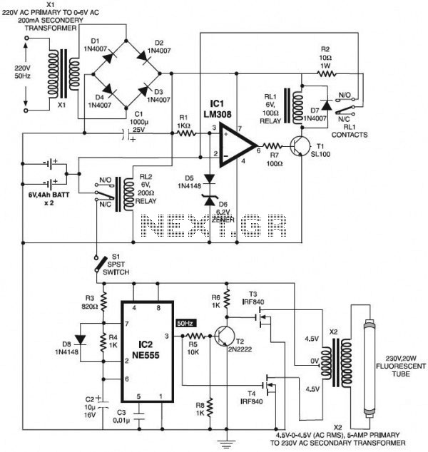
Automatic Emergency Light
The circuit below is an automatic switch-on emergency light that utilizes an integrated circuit (IC) as an automatic controller, along with an overcharge protection feature. This circuit is designed to drive the system effectively. Additionally, there is a VU meter...
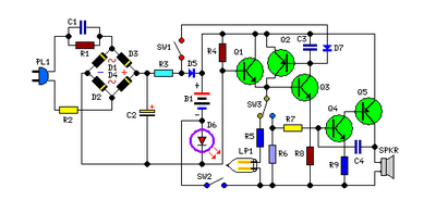
Emergency Light and Alarm
This circuit is permanently connected to a mains socket for the trickle charging of Ni-Cd batteries. In the event of a power outage, the lamp automatically turns on. Alternatively, an alarm sounder can be selected instead of the lamp. When...
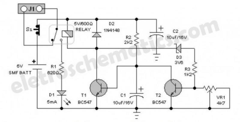
Battery Guard for Emergency Lights
An emergency light is a light source designed to be available during emergencies. It operates automatically and is powered by a rechargeable battery.
An emergency light system typically consists of several key components: a light source, a rechargeable battery, a charging...
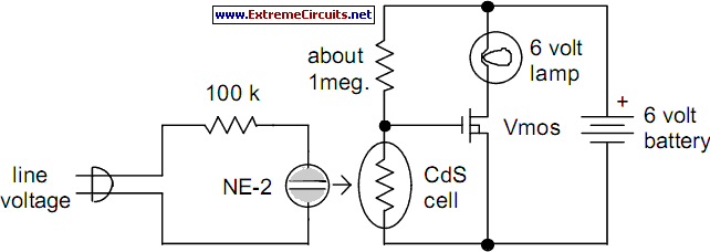
Backup Lamp
There are several situations where a power failure can be particularly challenging to manage, especially in the bathroom. This compact circuit is designed to be cost-effective, particularly beneficial during a shower. The backup lamp remains off as long as light...
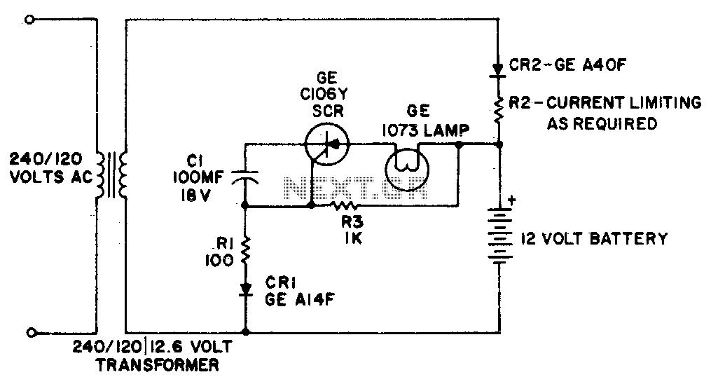
Emergency light
This simple circuit provides battery-operated emergency lighting instantaneously upon failure of the regular AC service. When line power is restored, the emergency light turns off and the battery recharges automatically. The circuit is ideal for use in elevator cars, corridors,...
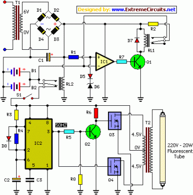
Emergency Light With Battery Charger
The following circuit illustrates an Emergency Light with a Battery Charger Circuit Diagram. Features include automatic activation of the light when mains power is available.
The Emergency Light with Battery Charger Circuit is designed to provide illumination during power outages while...