


Dark-activated 230V Lamp

Description: This device allows one or more lamps to illuminate at sunset and turn off at dawn. Q1 and Q2 form a trigger device for the SCR, providing short pulses at 100Hz frequency. Pulse duration is set by R2 and C1. More: When the light hits R1, the photo resistor assumes a very low resistance value, almost shorting C1 and preventing circuit operation. When R1 is in the dark, its resistance value becomes very high thus enabling circuit operation.
The described circuit functions as an automatic lighting control system that activates lamps at dusk and deactivates them at dawn. The core components include two transistors (Q1 and Q2), a silicon-controlled rectifier (SCR), a photoresistor (R1), a resistor (R2), and a capacitor (C1).
Q1 and Q2 are configured to operate as a trigger circuit for the SCR, which is the primary switching device responsible for controlling the power to the lamps. The transistors are likely arranged in a Darlington pair configuration to amplify the signal from the photoresistor. This arrangement ensures that even a small change in light detected by R1 can result in a significant change in the output, allowing the SCR to turn on or off effectively.
The frequency of operation is set at 100Hz, which is determined by the values of R2 and C1. The pulse duration, which is the time the SCR remains in the conducting state, is also influenced by these components. R2 is a current-limiting resistor that works in conjunction with C1, a timing capacitor. The charging and discharging of C1 through R2 dictate the timing characteristics of the circuit.
R1, being a photoresistor, plays a critical role in sensing ambient light levels. During daylight, R1 exhibits low resistance, which effectively shorts C1, preventing it from charging and thus inhibiting the operation of the circuit. Conversely, in low-light conditions, R1's resistance increases significantly, allowing C1 to charge and enabling the circuit to function. This change in resistance is the key mechanism that triggers the SCR, allowing the connected lamps to illuminate.
Overall, this circuit serves as an efficient solution for automatic lighting control, utilizing basic electronic components to achieve reliable performance in response to changing light conditions. The design is suitable for outdoor lighting applications, such as garden lights or street lamps, where automatic operation enhances convenience and energy efficiency.This device allows one or more lamps to illuminate at sunset and turn off at dawn. Q1 and Q2 form a trigger device for the SCR, providing short pulses at 100Hz frequency. Pulse duration is set by R2 and C1. When the light hits R1, the photo resistor assumes a very low resistance value, almost shorting C1 and preventing circuit operation. When R1 is in the dark, its resistance value becomes very high thus enabling circuit operation.
The described circuit functions as an automatic lighting control system that activates lamps at dusk and deactivates them at dawn. The core components include two transistors (Q1 and Q2), a silicon-controlled rectifier (SCR), a photoresistor (R1), a resistor (R2), and a capacitor (C1).
Q1 and Q2 are configured to operate as a trigger circuit for the SCR, which is the primary switching device responsible for controlling the power to the lamps. The transistors are likely arranged in a Darlington pair configuration to amplify the signal from the photoresistor. This arrangement ensures that even a small change in light detected by R1 can result in a significant change in the output, allowing the SCR to turn on or off effectively.
The frequency of operation is set at 100Hz, which is determined by the values of R2 and C1. The pulse duration, which is the time the SCR remains in the conducting state, is also influenced by these components. R2 is a current-limiting resistor that works in conjunction with C1, a timing capacitor. The charging and discharging of C1 through R2 dictate the timing characteristics of the circuit.
R1, being a photoresistor, plays a critical role in sensing ambient light levels. During daylight, R1 exhibits low resistance, which effectively shorts C1, preventing it from charging and thus inhibiting the operation of the circuit. Conversely, in low-light conditions, R1's resistance increases significantly, allowing C1 to charge and enabling the circuit to function. This change in resistance is the key mechanism that triggers the SCR, allowing the connected lamps to illuminate.
Overall, this circuit serves as an efficient solution for automatic lighting control, utilizing basic electronic components to achieve reliable performance in response to changing light conditions. The design is suitable for outdoor lighting applications, such as garden lights or street lamps, where automatic operation enhances convenience and energy efficiency.This device allows one or more lamps to illuminate at sunset and turn off at dawn. Q1 and Q2 form a trigger device for the SCR, providing short pulses at 100Hz frequency. Pulse duration is set by R2 and C1. When the light hits R1, the photo resistor assumes a very low resistance value, almost shorting C1 and preventing circuit operation. When R1 is in the dark, its resistance value becomes very high thus enabling circuit operation.
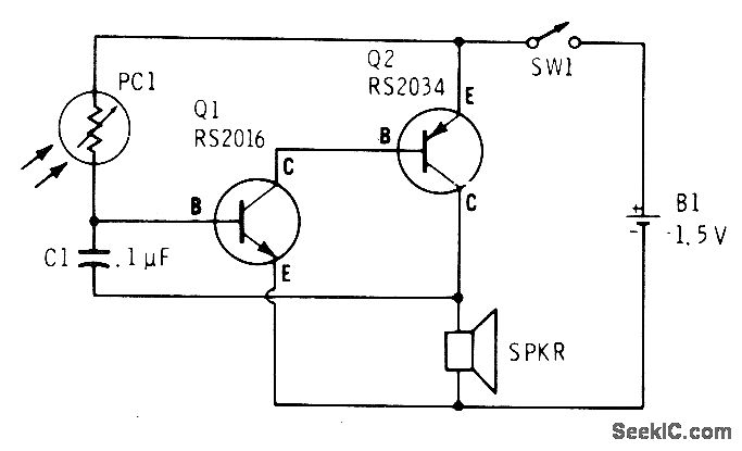
AUDIBLE LIGHT METER
A low light condition on a cadmium sulfide photocell (Radio Shack 276-116) generates a series of clicks in a miniature 8-ohm loudspeaker. As the light intensity increases, these clicks coalesce into an audio tone that escalates in frequency with rising...
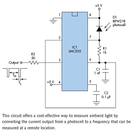
Simple Light Sensor Circuit Features High Dynamic Range
Ambient light is increasingly being utilized as an energy source. To assist designers in developing such systems, this circuit effectively measures ambient light intensity across four decades of measurement. The design is cost-effective, and with the sensor housed in a...
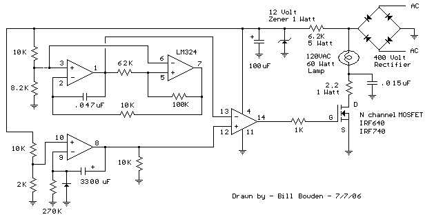
sunrise lamp
This circuit gradually illuminates a 120VAC lamp over an approximate 20-minute period. A bridge rectifier provides 120V DC to the MOSFET and the 60-watt lamp. A 6.2K, 5-watt resistor along with a Zener diode is utilized to reduce the voltage...
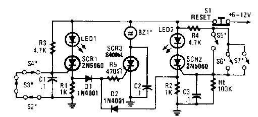
scr high power alarm driver circuit design
A straightforward high-power alarm driver electronic project can be developed using this circuit diagram. This high-power alarm driver project utilizes a low-power SCR to trigger a high-power SCR. When switches S2, S3, or S4 are opened or switches S5, S6,...
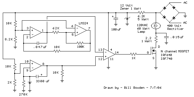
Sunrise Lamp circuit
This circuit gradually illuminates a 120VAC lamp over an approximate 20-minute period. A bridge rectifier converts the AC voltage to 120V DC, supplying power to the MOSFET and the 60-watt lamp. A 6.2K, 5-watt resistor along with a Zener diode...
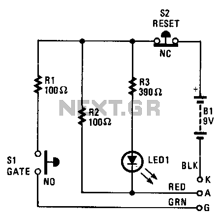
Scr-tester
The cathode, anode, and gate of the Device Under Test (DUT) are connected to the unit's K, A, and G terminals, respectively. Pressing switch S1 supplies a gate current to the DUT, triggering it to turn on. Resistor R1 limits...
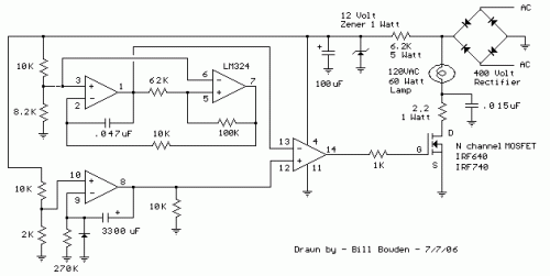
Sunrise Lamp
This circuit gradually illuminates a 120VAC lamp over an approximate 20-minute period. A bridge rectifier provides 120V DC to the MOSFET and the 60-watt lamp. A 6.2K, 5-watt resistor and a zener diode are employed to reduce the voltage to...
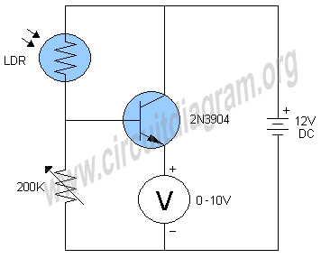
light intensity meter
This simple light intensity meter circuit can be used to determine the intensity of light in a wide variety of electronic projects and experiments.
The light intensity meter circuit is designed to measure ambient light levels and can be employed in...
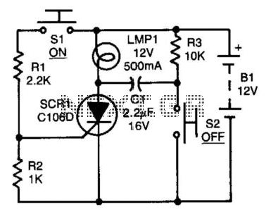
Scr Capacitor Turn-Off Circuit
After the SCR is activated, capacitor CI charges up to nearly the full supply voltage through resistor R3 and the anode of the SCR. When switch S2 is later closed, it grounds the positive terminal of CI, causing the charge...