


Fluorescent Lamp Driver Circuit and Project
#fluorescent lamp
#inverter
#12V driver
#efficiency
#circuit design
#power electronics
#lighting control
#energy saving
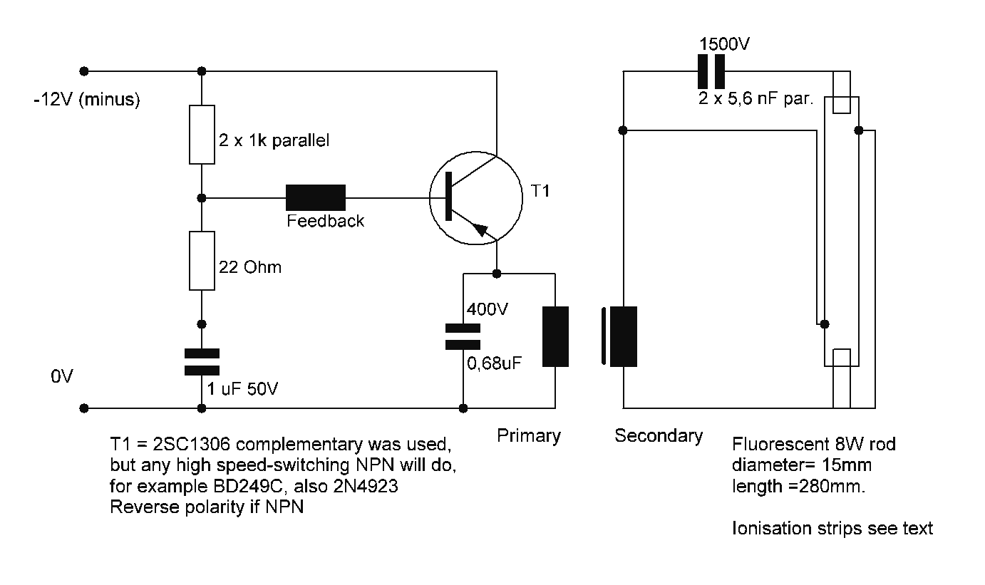
Description: Starting a fluorescent lamp on an inverter can be challenging due to the trade-offs involved in achieving optimal operating efficiency with 12V drivers.
Fluorescent lamps require a specific starting voltage to ionize the gas within the tube and initiate the lighting process. In inverter applications, particularly those utilizing 12V systems, the challenge lies in providing sufficient starting voltage while maintaining energy efficiency.
An inverter circuit designed for fluorescent lamps typically includes several essential components: a DC-DC converter, a high-frequency oscillator, and a transformer. The DC-DC converter steps up the 12V input to a higher voltage necessary for starting the lamp, often reaching levels around 400V to 600V. The high-frequency oscillator generates a pulse-width modulated (PWM) signal that drives the transformer, allowing for efficient energy transfer and higher output voltage.
The transformer used in this application is crucial; it must be designed to handle the high-frequency operation and provide isolation between the high-voltage output and the low-voltage input. Additionally, the design may include feedback mechanisms to regulate the output voltage and current, ensuring stable operation as the lamp warms up and reaches its steady state.
To enhance efficiency, the inverter may incorporate features such as soft-start circuits, which gradually increase the voltage applied to the lamp, reducing stress on the lamp and extending its lifespan. Furthermore, the circuit may include protective components like fuses or circuit breakers to prevent damage from overcurrent conditions during startup.
In summary, designing a 12V driver for fluorescent lamps on an inverter involves careful consideration of voltage requirements, component selection, and efficiency optimization to ensure reliable operation and longevity of the lamp.Starting a fluorescent on an inverter The 12V drivers for fluorescent lamps are tricky, because of the compromise between a good operating efficiency
Fluorescent lamps require a specific starting voltage to ionize the gas within the tube and initiate the lighting process. In inverter applications, particularly those utilizing 12V systems, the challenge lies in providing sufficient starting voltage while maintaining energy efficiency.
An inverter circuit designed for fluorescent lamps typically includes several essential components: a DC-DC converter, a high-frequency oscillator, and a transformer. The DC-DC converter steps up the 12V input to a higher voltage necessary for starting the lamp, often reaching levels around 400V to 600V. The high-frequency oscillator generates a pulse-width modulated (PWM) signal that drives the transformer, allowing for efficient energy transfer and higher output voltage.
The transformer used in this application is crucial; it must be designed to handle the high-frequency operation and provide isolation between the high-voltage output and the low-voltage input. Additionally, the design may include feedback mechanisms to regulate the output voltage and current, ensuring stable operation as the lamp warms up and reaches its steady state.
To enhance efficiency, the inverter may incorporate features such as soft-start circuits, which gradually increase the voltage applied to the lamp, reducing stress on the lamp and extending its lifespan. Furthermore, the circuit may include protective components like fuses or circuit breakers to prevent damage from overcurrent conditions during startup.
In summary, designing a 12V driver for fluorescent lamps on an inverter involves careful consideration of voltage requirements, component selection, and efficiency optimization to ensure reliable operation and longevity of the lamp.Starting a fluorescent on an inverter The 12V drivers for fluorescent lamps are tricky, because of the compromise between a good operating efficiency
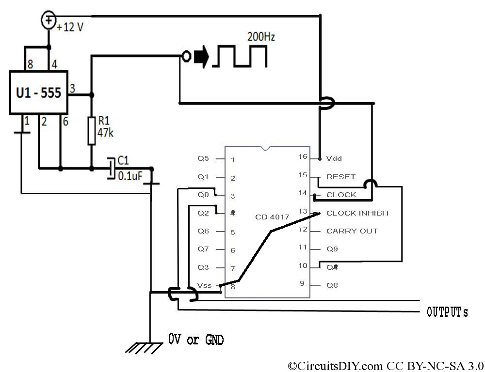
simplest modified sinewave inverter without microcontroller
Most inverters available in the market utilize a modified sine wave to achieve better output at a competitive cost. The modified sine wave unit employs a 50% fixed PWM square wave, with the peaks balanced by a capacitor to approximate...
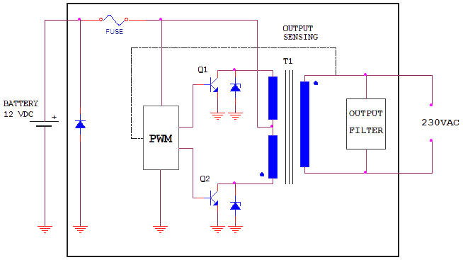
HR Diemen
An inverter, also known as an ondulator, is an electronic circuit designed to convert direct current (DC) into alternating current (AC). Its primary function is to alter the input voltage of direct current—typically sourced from a 12 or 24 V...
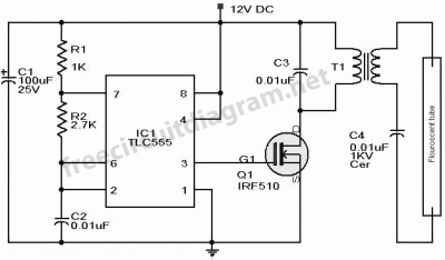
12V DC Fluorescent Lamp Circuit
This article presents a driver circuit for a 12V, 5W fluorescent lamp. The circuit utilizes a standard 220V to 10V step-down transformer operated in reverse to achieve a 12V output.
The driver circuit for a 12V, 5W fluorescent lamp is designed...
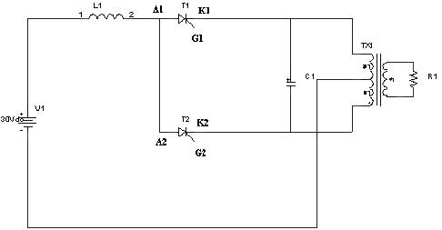
parallel inverter
The inverter plays a crucial role in Uninterrupted Power Supply (UPS) systems. It is responsible for converting direct current (DC) into alternating current (AC) at the required voltage. The fundamental configuration of a single-phase parallel inverter circuit comprises two silicon-controlled...
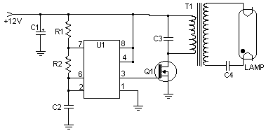
12VDC Fluorescent Lamp Driver
A number of people have been unable to find the transformer needed for the Black Light project, so I looked around to see if I could find a fluorescent lamp driver that does not require any special components. I finally...
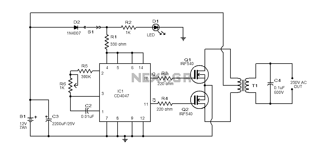
Simple 100W inverter schematic design
This document provides an explanation of a simple 100-watt inverter circuit using the IC CD4047 and the IRF540 MOSFET. The circuit is designed to be simple, cost-effective, and suitable for assembly on a veroboard. The CD4047 is a low-power CMOS...
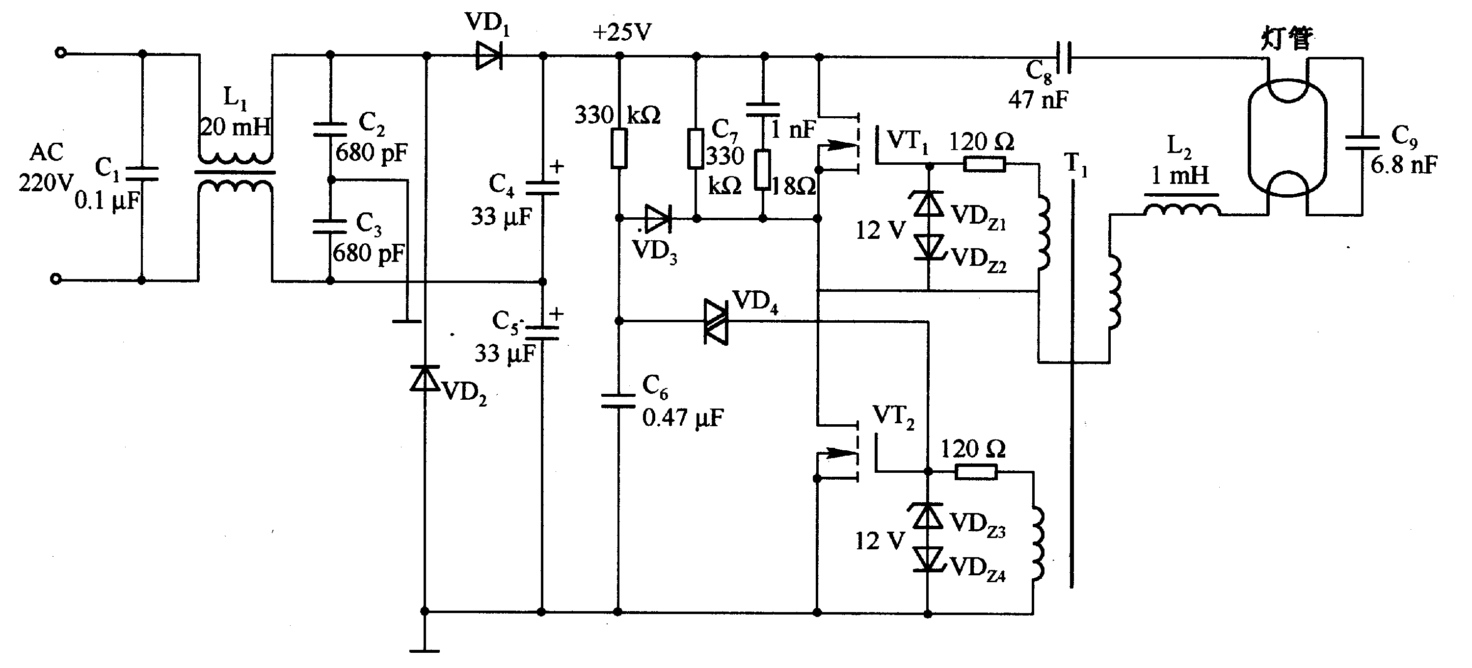
Fluorescent lamp driver circuit composed of FET
A fluorescent tube is connected in an LC resonant circuit consisting of inductor L2 and capacitor C9. The bidirectional breakdown diode VD4 initiates the starting circuit. When AC power is applied, the gate potential of transistor VT2 increases due to...
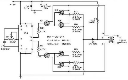
100W Inverter
The schematic diagram of a 100W inverter circuit converts a 12V DC input to a 220V AC output. The circuit is built using the CD4047 integrated circuit, which generates a sine wave signal at 50Hz. The power transistor 2N3055 amplifies...
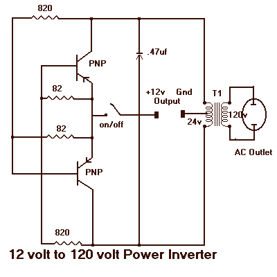
12 to 120 Volt Inverter
It will supply 15 watts of AC power to a device. It should power lamps, shavers, small stereos and small appliances. If you draw too much power the circuit will shut down all by itself. The output of this circuit...