


Lantern controller circuit diagram of a non-contact
#non-contact control
#thyristor
#music IC
#lantern
#drive circuit
#SCR
#BG1
#BG2
#controller
#lighting control
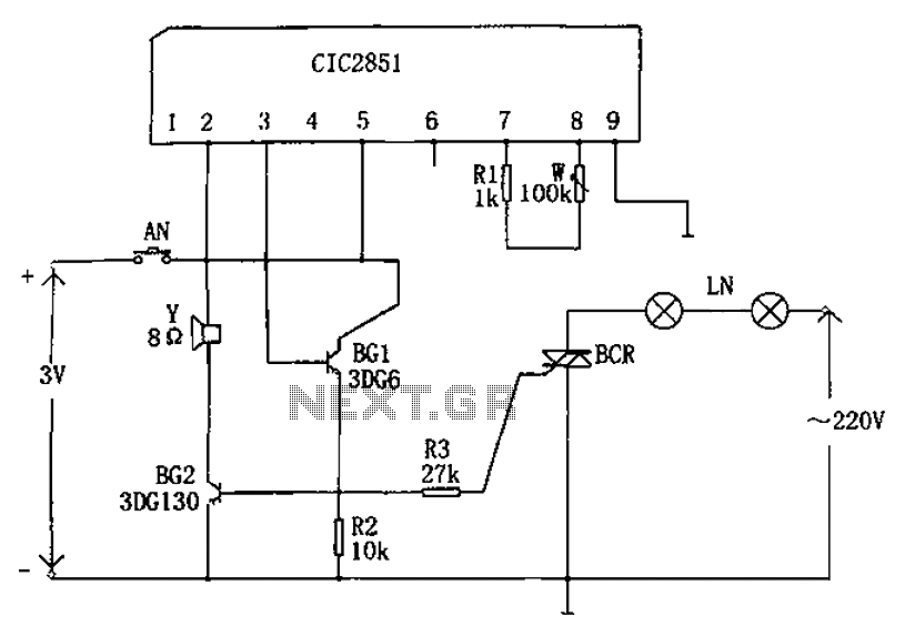
Description: The non-contact lantern control circuit includes an integrated music IC (CIC2851), transistors (BG1 and BG2), a thyristor (SCR), and other components. When the switch is pressed (AN), the CIC2851 is activated, causing the output terminal (pin 3) to emit a music signal. This signal is amplified by BG1 and BG2 to drive a speaker that plays the music. Simultaneously, the SCR is triggered, allowing current to flow through the lantern chain (LN). The conduction angle of the SCR changes with varying musical signal frequencies and intensities, causing the lights to flash in sync with the rhythm of the music. The circuit includes a music playing time adjustment feature that allows for modification of the flashing duration of the lights. Resistor R3 can be adjusted to change the intensity of the SCR trigger signal, enabling the lights to flash more vibrantly with careful tuning. Each press of the AN switch plays a piece of music, and the lights will flash for a set duration. If the AN switch is replaced with a toggle switch, the music will play continuously, and the lights will flash in succession. The integrated music circuit can be substituted with other models, while transistors BG1 and BG2 should be of the types 3DG6 and 3DG130, respectively, and the SCR can be a 3CTS3A/400V. The lantern chain can consist of commercially available products. This circuit effectively synchronizes light patterns with music, enhancing the enjoyment of musical performances and festive occasions.
The non-contact lantern control circuit is designed to provide an engaging audio-visual experience by synchronizing light output with musical signals. Central to the operation of this circuit is the CIC2851 integrated music circuit, which generates audio signals that are essential for driving the connected speaker. The transistors BG1 and BG2 serve as amplifiers that boost the audio signal to a sufficient level to drive the speaker effectively.
The SCR plays a crucial role in controlling the lantern chain (LN). When the SCR is triggered, it allows current to flow through the lanterns, illuminating them. The SCR's conduction angle is modulated based on the frequency and intensity of the audio signal, creating a dynamic lighting effect that corresponds to the rhythm of the music. This feature enhances the overall aesthetic experience, making it suitable for various events where music and lighting coordination is desired.
The circuit also incorporates a time adjustment mechanism, allowing users to control how long the lights flash in response to the music. This can be particularly useful for creating specific moods or themes during performances or celebrations. The adjustable resistor R3 provides further control over the SCR's trigger intensity, enabling fine-tuning of the lighting effects to achieve the desired vibrancy and responsiveness.
The design is flexible, allowing for the substitution of different music ICs, which can accommodate various audio output requirements. The specified transistors and SCR types ensure that the circuit operates reliably and efficiently, while the use of commercially available lantern chains makes implementation straightforward.
Overall, this circuit offers a creative solution for integrating light and sound, providing an entertaining and visually appealing experience that can enhance gatherings, parties, and other festive occasions. As shown below for the non-contact lantern control circuit. The controller includes integrated music CIC2851, drive BG1 and BG2, thyristor SCR and other components. When the sw itch is pressed AN, CIC2851 job is triggered, the output terminal (pin 3) output music signal that after BG1 and BG2 amplification drive the speaker sound of music. Meanwhile, the triac is triggered SCR conduction, the lantern lit chain LN. With different musical signal frequency and intensity of, SCR conduction angle is changed, so that the chain of lights with the music rhythm changes and issue the appropriate light.
W change music playing time adjustment circuit, you can change the time flashing lights chain. R3 may also be changed to adjust the intensity of SCR trigger signal, if carefully debugging, will enable the chain of lights flashing up the most lively. Each time you press AN, playing a piece of music, lights flashing along the chain for some time. If the AN switch replaced and closed, continuous music playing, lights chain will continuously flash.
Music integrated circuit may be replaced with other models, transistor BG1 and BG2 are 3DG6 and 3DG130 type requires its 60, SCR can be used 3CTS3A/400V. Lantern chain selected commercial products. This circuit can achieve bright lights off with the rhythm of the music changes, and can make people enjoy the melodious music, which can be used to add programs and joy of the occasion.
The non-contact lantern control circuit is designed to provide an engaging audio-visual experience by synchronizing light output with musical signals. Central to the operation of this circuit is the CIC2851 integrated music circuit, which generates audio signals that are essential for driving the connected speaker. The transistors BG1 and BG2 serve as amplifiers that boost the audio signal to a sufficient level to drive the speaker effectively.
The SCR plays a crucial role in controlling the lantern chain (LN). When the SCR is triggered, it allows current to flow through the lanterns, illuminating them. The SCR's conduction angle is modulated based on the frequency and intensity of the audio signal, creating a dynamic lighting effect that corresponds to the rhythm of the music. This feature enhances the overall aesthetic experience, making it suitable for various events where music and lighting coordination is desired.
The circuit also incorporates a time adjustment mechanism, allowing users to control how long the lights flash in response to the music. This can be particularly useful for creating specific moods or themes during performances or celebrations. The adjustable resistor R3 provides further control over the SCR's trigger intensity, enabling fine-tuning of the lighting effects to achieve the desired vibrancy and responsiveness.
The design is flexible, allowing for the substitution of different music ICs, which can accommodate various audio output requirements. The specified transistors and SCR types ensure that the circuit operates reliably and efficiently, while the use of commercially available lantern chains makes implementation straightforward.
Overall, this circuit offers a creative solution for integrating light and sound, providing an entertaining and visually appealing experience that can enhance gatherings, parties, and other festive occasions. As shown below for the non-contact lantern control circuit. The controller includes integrated music CIC2851, drive BG1 and BG2, thyristor SCR and other components. When the sw itch is pressed AN, CIC2851 job is triggered, the output terminal (pin 3) output music signal that after BG1 and BG2 amplification drive the speaker sound of music. Meanwhile, the triac is triggered SCR conduction, the lantern lit chain LN. With different musical signal frequency and intensity of, SCR conduction angle is changed, so that the chain of lights with the music rhythm changes and issue the appropriate light.
W change music playing time adjustment circuit, you can change the time flashing lights chain. R3 may also be changed to adjust the intensity of SCR trigger signal, if carefully debugging, will enable the chain of lights flashing up the most lively. Each time you press AN, playing a piece of music, lights flashing along the chain for some time. If the AN switch replaced and closed, continuous music playing, lights chain will continuously flash.
Music integrated circuit may be replaced with other models, transistor BG1 and BG2 are 3DG6 and 3DG130 type requires its 60, SCR can be used 3CTS3A/400V. Lantern chain selected commercial products. This circuit can achieve bright lights off with the rhythm of the music changes, and can make people enjoy the melodious music, which can be used to add programs and joy of the occasion.
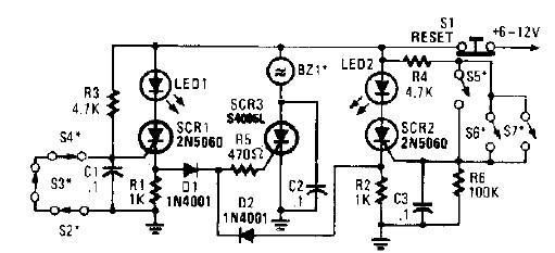
scr high power alarm driver circuit design
A straightforward high-power alarm driver electronic project can be developed using this circuit diagram. This high-power alarm driver project utilizes a low-power SCR to trigger a high-power SCR. When switches S2, S3, or S4 are opened or switches S5, S6,...
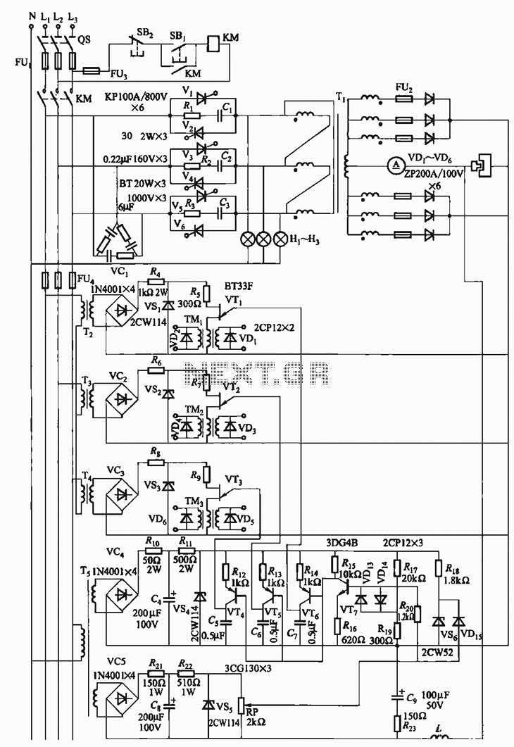
300A-18V three-phase thyristor power regulator circuit for electrolysis
The 300A-18V three-phase thyristor power regulator circuit is designed for electrolysis applications. It can output a direct current of 3000A at an adjustable voltage of 18V, providing a power supply solution for various processing needs. The circuit comprises a main...
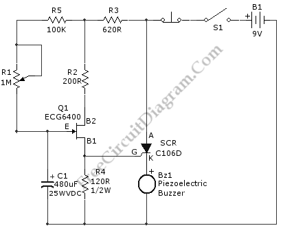
Long Period SCR Timer
This is an SCR timer circuit. In this circuit, an SCR is utilized to activate the final actuator, which is a buzzer. The time constant of the circuit is determined by resistor R1 and capacitor C1. The buzzer will sound...
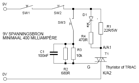
Thyristor / TRIAC Tester
This is a simple but effective thyristor TRIAC tester. Operation at a good thyristor/triac: LED lights when SW3 is pressed. LED turns off when SW2 is pressed. If this occurs, the thyristor/triac is OK. Tip: Hirschmann clips for the tested...
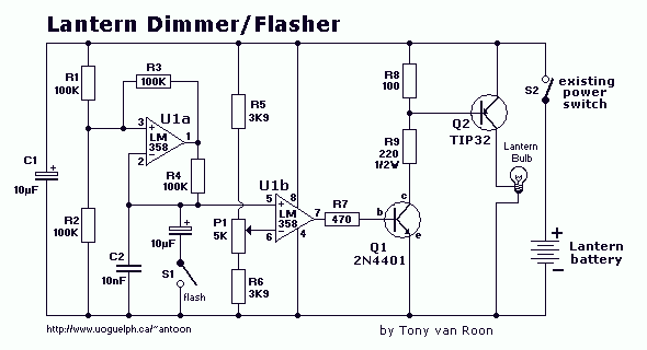
Lantern with dimmer and flasher
The electronic lantern control circuit adds high-efficiency dimming and flashing to an existing battery-powered lantern or flashlight or to a custom design. For the car it makes a great lamp for changing a flat tire, back seat reading or emergency...
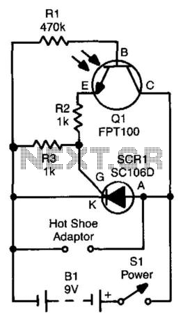
Slave Flash Trigger
The SCR is connected across the trigger circuit of the flash gun. In its default state, the SCR remains off, allowing the flash gun to charge to its trigger voltage. A phototransistor, Q1, is utilized to monitor the light level....
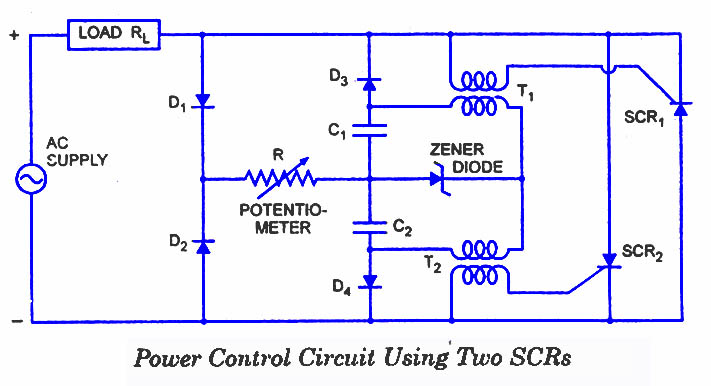
SCR Applications
The ability of an SCR to control large currents to a load using a small gate current makes the device highly useful in switching and control applications. Several potential applications for the SCR include power control, switching, zero-voltage switching, over-voltage...
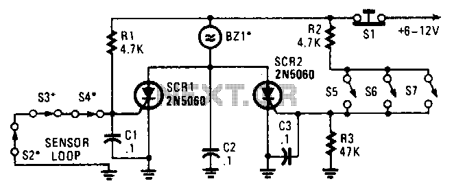
Series Parallel Loop Alarm Circuit
Two SCRs are utilized with two sensor loops. One loop employs series switches, while the other loop employs parallel switches. When a switch is actuated, the SCR is triggered. The alarm is designed to be a non-interrupting type.
The circuit described...
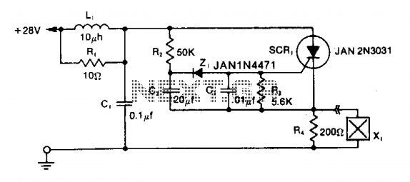
Squib-firing circuit 2
The LRC input network limits the anode dv/dt to a safe value below 30 V/μs. Rl provides critical damping to prevent voltage overshoot. While a simple RC filter section could be used, the high current required by the squib would...