


Photo Strobe Circuit
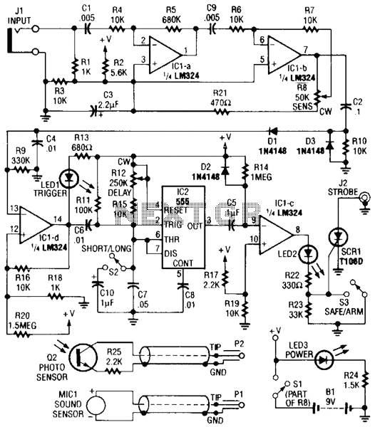
Description: Sound or light sensors connected to J2 produce a voltage that is amplified by IC1-a and IC1-b. A positive trigger voltage developed by D1 and R3, and amplified by IC1-d, drives IC2 and IC1 to trigger SCR1. SCR1 is connected to a strobe. This device is useful for photographic purposes to capture images of events that involve sound, such as impacts, etc.
The circuit consists of several key components that work together to detect sound or light and trigger a strobe light for photographic purposes. The sound or light sensors connected to connector J2 generate an initial voltage signal in response to environmental stimuli. This voltage is then fed into two operational amplifiers, IC1-a and IC1-b, which serve to amplify the signal to a usable level.
The amplified signal is processed further to generate a positive trigger voltage. This is achieved through the diode D1 and resistor R3, which work in conjunction with operational amplifier IC1-d. The role of IC1-d is to further amplify the trigger voltage, ensuring that it is strong enough to drive subsequent components in the circuit.
The output from IC1-d is connected to two additional integrated circuits, IC2 and IC1, which are configured to control the triggering mechanism of the silicon-controlled rectifier (SCR1). SCR1 acts as a switch that controls the power to the strobe light. When the trigger voltage reaches a certain threshold, SCR1 is activated, allowing current to flow to the strobe, thereby producing a flash of light.
This circuit is particularly advantageous for capturing images of dynamic events that are difficult to photograph using conventional methods. The ability to synchronize the strobe with sound or light events enables photographers to capture precise moments, such as impacts or other rapid occurrences, making it a valuable tool in various photographic applications. Sound or light sensors corniected to J2 produce a voltage that is amplified by ICl-a and ICl-b. A positive trigger voltage that is developed by D1 and 1)3 and amplified by ICl-d, drives 1C2 and 1C1 to trigger SCR1. SCR1 is connected to a strobe. This device is handy for photographic purposes to take pictures of events that involve sound, such as impacts, ctc.
The circuit consists of several key components that work together to detect sound or light and trigger a strobe light for photographic purposes. The sound or light sensors connected to connector J2 generate an initial voltage signal in response to environmental stimuli. This voltage is then fed into two operational amplifiers, IC1-a and IC1-b, which serve to amplify the signal to a usable level.
The amplified signal is processed further to generate a positive trigger voltage. This is achieved through the diode D1 and resistor R3, which work in conjunction with operational amplifier IC1-d. The role of IC1-d is to further amplify the trigger voltage, ensuring that it is strong enough to drive subsequent components in the circuit.
The output from IC1-d is connected to two additional integrated circuits, IC2 and IC1, which are configured to control the triggering mechanism of the silicon-controlled rectifier (SCR1). SCR1 acts as a switch that controls the power to the strobe light. When the trigger voltage reaches a certain threshold, SCR1 is activated, allowing current to flow to the strobe, thereby producing a flash of light.
This circuit is particularly advantageous for capturing images of dynamic events that are difficult to photograph using conventional methods. The ability to synchronize the strobe with sound or light events enables photographers to capture precise moments, such as impacts or other rapid occurrences, making it a valuable tool in various photographic applications. Sound or light sensors corniected to J2 produce a voltage that is amplified by ICl-a and ICl-b. A positive trigger voltage that is developed by D1 and 1)3 and amplified by ICl-d, drives 1C2 and 1C1 to trigger SCR1. SCR1 is connected to a strobe. This device is handy for photographic purposes to take pictures of events that involve sound, such as impacts, ctc.
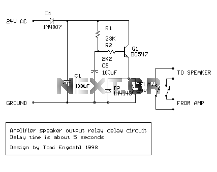
amplifier delay output relay
This is a simple circuit which I built to one of my audio amplifier projects to control the speaker output relay. The purpose of this circuit is to control the relay which turns on the speaker output relay in the...
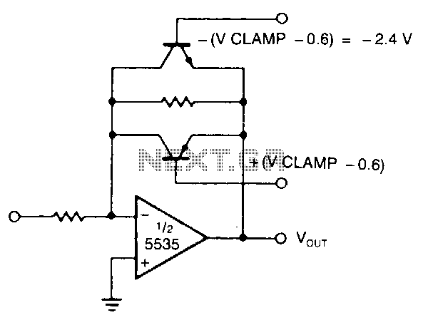
Active-limiting-amplifier
The modified inverting amplifier employs an active clamp to precisely limit the output swing. Consideration must be given to the VBE of the transistors. The output swing is restricted by the base-emitter breakdown of the transistors. A straightforward circuit configuration...
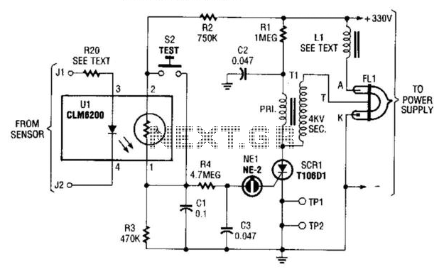
Strobe Alarm
This strobe provides a visual indication of a sensor input. The input signal causes the light-dependent resistor (LDR) to change the charge across capacitors C1 and C3 through resistor R4. When NE1 fires, capacitor C3 discharges into SCR1, triggering it...
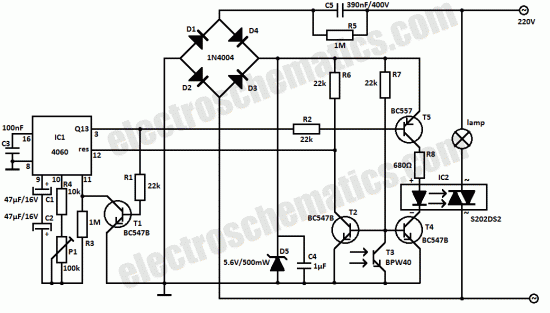
Light sensor switch circuit
This light sensor switch circuit enables the automatic activation of a lamp when ambient light levels are low, such as during nighttime. The circuit keeps the lamp illuminated for a predetermined duration. When transistors T4 and T5 are activated, the...
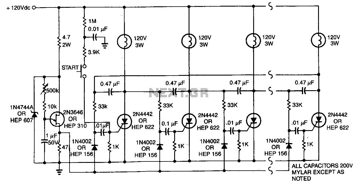
Scr-ring-counter
One lamp at a time is lit in the string to give the appearance of a moving point of light. More: The ring counter circuit.
The described circuit utilizes a ring counter configuration to create a sequential lighting effect in which...
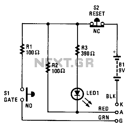
Scr-tester
The cathode, anode, and gate of the Device Under Test (DUT) are connected to the unit's K, A, and G terminals, respectively. Pressing switch S1 supplies a gate current to the DUT, triggering it to turn on. Resistor R1 limits...
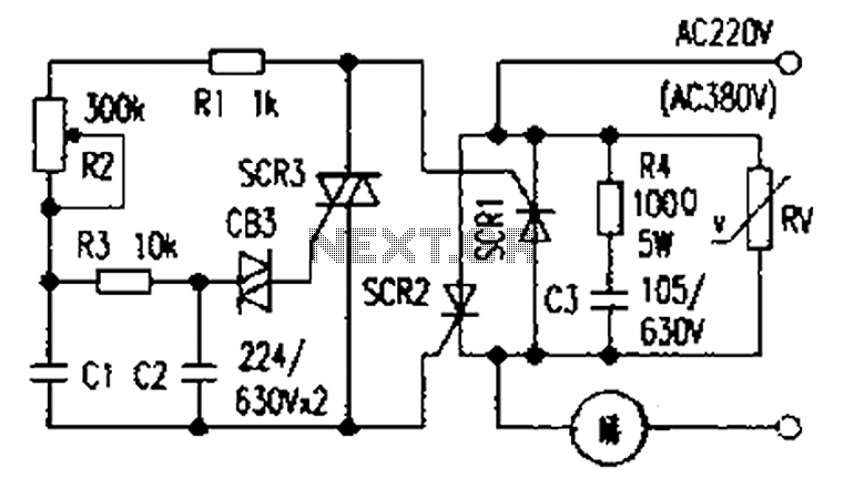
Simple and practical power SCR trigger circuit diagram
The presentation of a general power thyristor trigger circuit is more complex, and some components are difficult to procure. A successful trigger circuit has been constructed for only a few dollars. This circuit is designed to trigger a thyristor module...
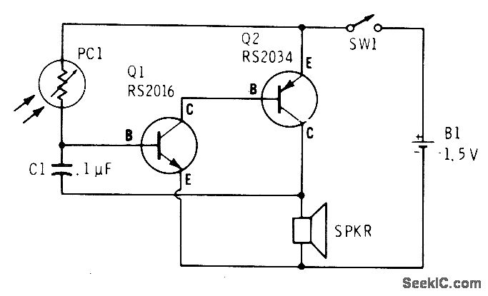
AUDIBLE LIGHT METER
A low light condition on a cadmium sulfide photocell (Radio Shack 276-116) generates a series of clicks in a miniature 8-ohm loudspeaker. As the light intensity increases, these clicks coalesce into an audio tone that escalates in frequency with rising...
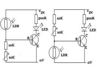
Light Follower Robot
The figures above illustrate the fundamental concept of a robot, which consists of various input and output devices connected to a central processing unit, commonly referred to as the brain. These inputs and outputs are essential for the robot's functionality...