


Photo Strobe Slave Trigger Circuit
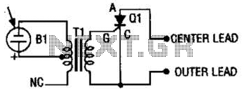
Description: The photo strobe slave trigger circuit utilizes a solar cell and a silicon-controlled rectifier (SCR) to activate any strobe light when triggered by a master strobe. The small solar cell generates a minimal voltage when illuminated.
The photo strobe slave trigger circuit operates by harnessing the energy from ambient light to initiate a flash in response to a primary strobe light source. The solar cell, typically a small photovoltaic cell, converts light energy into electrical energy, producing a voltage output that is proportional to the intensity of the light it receives. When the master strobe is activated, it emits a burst of light that strikes the solar cell.
Upon receiving this light, the solar cell generates a small voltage, which is sufficient to trigger the SCR. The SCR, a semiconductor device that acts as a switch, remains off until it is triggered by a voltage applied to its gate terminal. Once the SCR is activated by the voltage from the solar cell, it allows current to flow through the strobe light circuit, causing the connected strobe to flash.
This circuit design is advantageous for photographers who require multiple flashes synchronized with a primary light source without the need for complex wiring or additional triggering mechanisms. The simplicity of the solar cell-based trigger allows for portability and ease of use in various lighting conditions. Additionally, the use of an SCR provides reliable switching capabilities, ensuring that the strobe light will flash promptly when triggered.
Overall, the photo strobe slave trigger circuit exemplifies an efficient and innovative solution for enhancing photographic lighting setups, enabling photographers to achieve creative effects with minimal equipment. The photo strobe slave trigger circuit uses a solar cell and an SCR to flash any strobe when you trigger your master strobe. The tiny solar cell produces a very small voltage when light falls on its surface.
The photo strobe slave trigger circuit operates by harnessing the energy from ambient light to initiate a flash in response to a primary strobe light source. The solar cell, typically a small photovoltaic cell, converts light energy into electrical energy, producing a voltage output that is proportional to the intensity of the light it receives. When the master strobe is activated, it emits a burst of light that strikes the solar cell.
Upon receiving this light, the solar cell generates a small voltage, which is sufficient to trigger the SCR. The SCR, a semiconductor device that acts as a switch, remains off until it is triggered by a voltage applied to its gate terminal. Once the SCR is activated by the voltage from the solar cell, it allows current to flow through the strobe light circuit, causing the connected strobe to flash.
This circuit design is advantageous for photographers who require multiple flashes synchronized with a primary light source without the need for complex wiring or additional triggering mechanisms. The simplicity of the solar cell-based trigger allows for portability and ease of use in various lighting conditions. Additionally, the use of an SCR provides reliable switching capabilities, ensuring that the strobe light will flash promptly when triggered.
Overall, the photo strobe slave trigger circuit exemplifies an efficient and innovative solution for enhancing photographic lighting setups, enabling photographers to achieve creative effects with minimal equipment. The photo strobe slave trigger circuit uses a solar cell and an SCR to flash any strobe when you trigger your master strobe. The tiny solar cell produces a very small voltage when light falls on its surface.
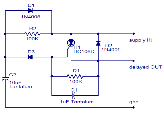
dc power delay based on scr
The circuit diagram presented illustrates a straightforward DC power delay circuit that utilizes a Silicon-Controlled Rectifier (SCR). This circuit is highly versatile and applicable in various scenarios. The operation is uncomplicated: when the input power is supplied, capacitor C2 charges...
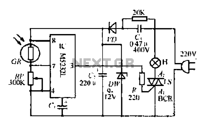
An automatic flash indicating circuit
The DW L11 capacitor steps down voltage into the Jenru half crossing according to Yin electrical specifications. After receiving power at the bin CI SH output terminal, it regulates the voltage to liVI/r j, ensuring a right cut in blood...
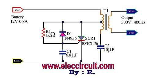
SCR Mini Power Inverter
This is a Mini Power Inverter that utilizes SCR as the main electronic component. It operates an oscillator generator at 400Hz, providing an output of 300V from a 12V input voltage.
The Mini Power Inverter is designed to convert a low...
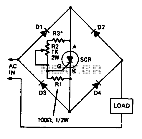
Full-wave scr control
This circuit allows a single Silicon Controlled Rectifier (SCR) to control resistive loads in a full-wave configuration. Resistor R3 must be selected to ensure that when potentiometer R2 is set to its minimum value, the current flowing through the load...
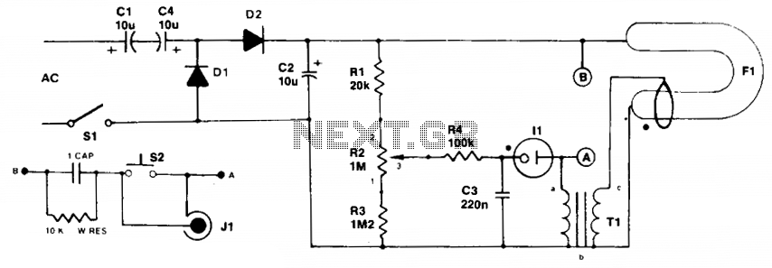
Simple strobe circuit
Initially, the neon and xenon lamps do not conduct and behave like very high (almost infinite) resistance. Capacitors C1 and C4, in conjunction with diodes D1 and D2, form a voltage doubler circuit, allowing C2 to charge up to approximately...
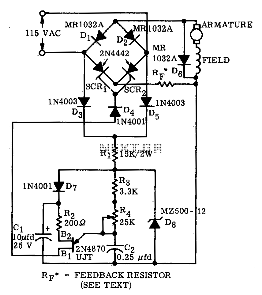
High-torque motor speed control
A bridge circuit consisting of two silicon-controlled rectifiers (SCRs) and two silicon rectifiers provides full-wave power to the motor. Diodes D3 and D5 deliver direct current (DC) to the trigger circuit through dropping resistors, R1. The phase delay of SCR...

First-Response Monitor with SCR (Quiz Alarm)
A pair of cross-coupled SCRs can be utilized to create a first-response monitor circuit, as illustrated in the schematic diagram below. The first-response circuit is...
In the context of electronic monitoring systems, a first-response monitor circuit employing cross-coupled Silicon Controlled Rectifiers...
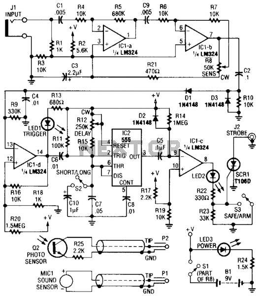
Photo Strobe Circuit
Sound or light sensors connected to J2 produce a voltage that is amplified by IC1-a and IC1-b. A positive trigger voltage developed by D1 and R3, and amplified by IC1-d, drives IC2 and IC1 to trigger SCR1. SCR1 is connected...
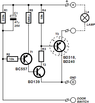
Vehicle Interior Lighting With Switch-Off Delay
Nowadays, a switch-off delay for vehicle interior lighting is a standard feature. However, certain models with minimal settings or older vehicles leave users in the dark as soon as they enter and close the door. This situation calls for an...