


SH-841 ASIC holiday lights
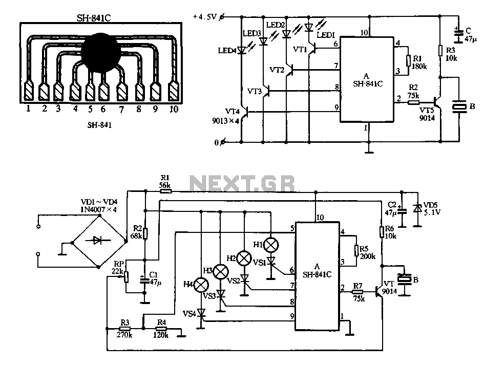
Description: Figure 2-78 illustrates the SH-841 as the central component in a holiday lights controller. It utilizes SCRs VS1 to VS4 to drive light strings H1 to H4, causing them to flash. The operating voltage is sourced from AC through the bridge rectifier formed by diodes VD1 to VD4, while resistor R1 functions as a buck converter. Diode VD5 and capacitor C2 are employed to filter and regulate the output. Additionally, a music signal output is generated via an amplifying transistor VT to drive a piezoelectric ceramic sheet B, producing sound. An adjustment potentiometer RP allows for control over the sound volume.
The circuit design described in Figure 2-78 serves as an effective holiday lights controller, integrating both visual and auditory effects. The SH-841 microcontroller is the heart of the system, managing the operation of the light strings. The SCRs (Silicon Controlled Rectifiers) VS1 to VS4 are crucial for controlling the flow of current to the light strings H1 to H4. These SCRs allow for the modulation of the light output, creating a flashing effect synchronized with a music signal.
The AC power supply is converted to a usable DC voltage through the bridge rectifier composed of diodes VD1 to VD4. This configuration ensures that the circuit can handle both halves of the AC waveform, providing a smooth DC output. Resistor R1 is used to step down the voltage to a safe level for the subsequent components. Diode VD5, in conjunction with capacitor C2, serves to filter out any ripple from the rectified voltage, ensuring a stable DC supply for the circuit's operation.
The audio component of the circuit is facilitated by the amplifying transistor VT, which boosts the music signal output. This amplified signal is then used to drive a piezoelectric ceramic sheet B, which converts the electrical signal into sound. The integration of sound with the visual elements of the holiday lights enhances the overall experience. The potentiometer RP provides user-adjustable control over the sound volume, allowing for customization based on user preference or ambient conditions.
Overall, the circuit exemplifies a well-designed integration of lighting and sound, suitable for festive decorations and events. The combination of SCRs for light control and a transistor for sound amplification showcases a practical application of electronic components in creating an engaging user experience.Figure 2-78 is SH-841 as the core device made holiday lights controller. By SCR VSl ~ VS4 to drive light string H1 ~ H4 flashes. Manifold operating voltage by AC by VD1-VD4 bri dge rectifier, Rl buck, VD5 filter regulator and C2 obtained. Manifold 2 feet of the music signal output by the amplifying transistor VT to drive the piezoelectric ceramic sheet B made sound. Adjustment potentiometer RP can control the sound volume.
The circuit design described in Figure 2-78 serves as an effective holiday lights controller, integrating both visual and auditory effects. The SH-841 microcontroller is the heart of the system, managing the operation of the light strings. The SCRs (Silicon Controlled Rectifiers) VS1 to VS4 are crucial for controlling the flow of current to the light strings H1 to H4. These SCRs allow for the modulation of the light output, creating a flashing effect synchronized with a music signal.
The AC power supply is converted to a usable DC voltage through the bridge rectifier composed of diodes VD1 to VD4. This configuration ensures that the circuit can handle both halves of the AC waveform, providing a smooth DC output. Resistor R1 is used to step down the voltage to a safe level for the subsequent components. Diode VD5, in conjunction with capacitor C2, serves to filter out any ripple from the rectified voltage, ensuring a stable DC supply for the circuit's operation.
The audio component of the circuit is facilitated by the amplifying transistor VT, which boosts the music signal output. This amplified signal is then used to drive a piezoelectric ceramic sheet B, which converts the electrical signal into sound. The integration of sound with the visual elements of the holiday lights enhances the overall experience. The potentiometer RP provides user-adjustable control over the sound volume, allowing for customization based on user preference or ambient conditions.
Overall, the circuit exemplifies a well-designed integration of lighting and sound, suitable for festive decorations and events. The combination of SCRs for light control and a transistor for sound amplification showcases a practical application of electronic components in creating an engaging user experience.Figure 2-78 is SH-841 as the core device made holiday lights controller. By SCR VSl ~ VS4 to drive light string H1 ~ H4 flashes. Manifold operating voltage by AC by VD1-VD4 bri dge rectifier, Rl buck, VD5 filter regulator and C2 obtained. Manifold 2 feet of the music signal output by the amplifying transistor VT to drive the piezoelectric ceramic sheet B made sound. Adjustment potentiometer RP can control the sound volume.
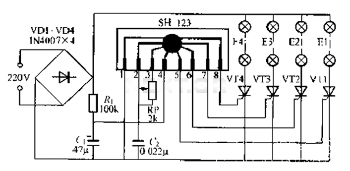
Four flashing lights string circuit 6
A water Happy Valley-type four flashing lights string controller, electric bollard is designed for use with a type J Ding Japanese lantern. The circuit employs a specific integrated circuit (IC) utilizing CMOS technology. It features a black soft cream package...
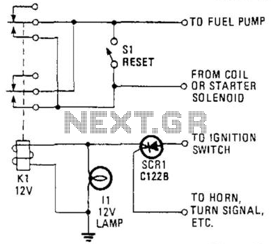
Auto Ignition Cut-Off
This circuit utilizes a combination of a silicon-controlled rectifier (SCR) and a relay to interrupt the ignition system unless a positive voltage is applied to the gate of the SCR. This configuration serves as an anti-theft device, as the vehicle...
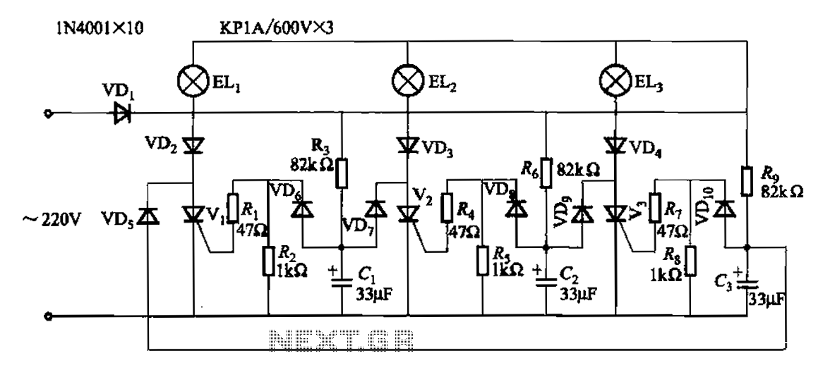
A plurality of sets of three loop flashing lights chain circuits
The circuit operates with a 220V mains supply through a diode (VDi) configured as a half-wave rectifier. Capacitors C1 to C3 are charged, and due to the lack of full synchronization in the charging process, a pilot thyristor is required...
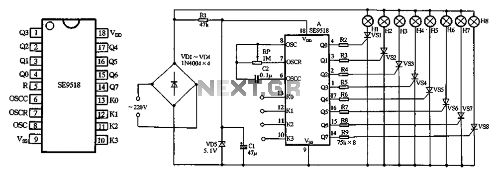
SE9518 holiday lights ASIC
The circuit utilizes a 220V AC input, which is processed through a VD1-VD4 bridge rectifier to convert the AC voltage into a DC voltage. This DC voltage is then used to power eight lights labeled H1 to H8. Additionally, a...
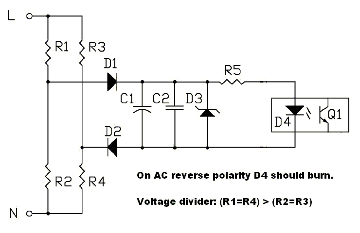
AC polarity detection
The circuit should be capable of detecting voltages between 230 VAC and 120 VAC to 250 VAC, making it suitable for both US and EU applications. A non-isolated circuit was found, but it fails to simulate correctly due to ground...
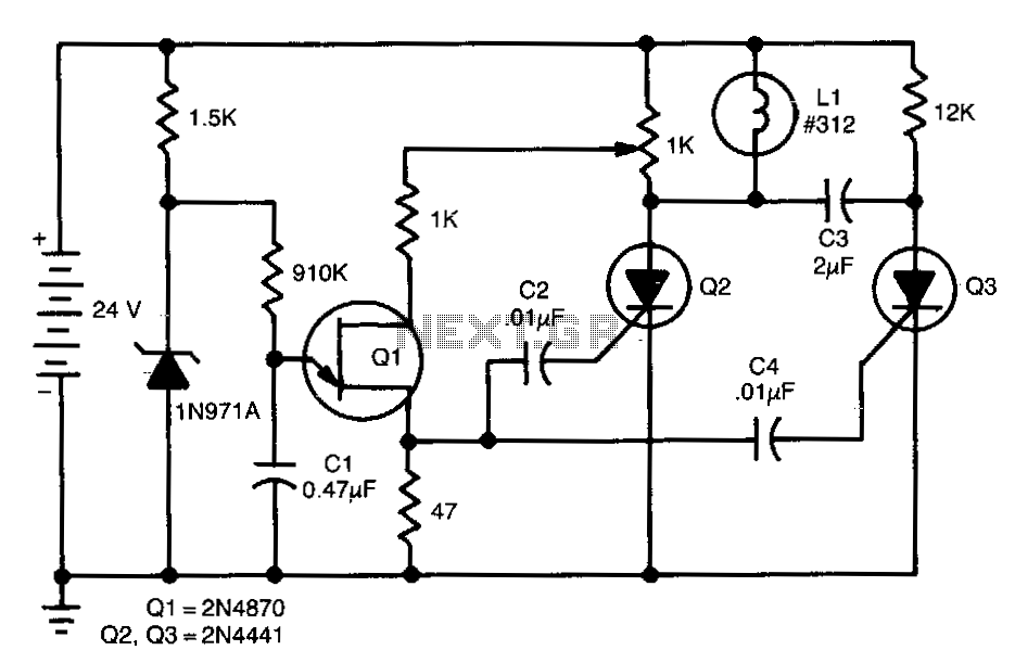
Scr-flasher
This de-flasher utilizes two SCRs and a unijunction oscillator clock to establish the flash rate, which can be adjusted by modifying the value of C1.
The circuit described operates as a de-flasher, a device commonly used in lighting applications to...
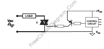
SCR And Triac Triggering Circuit With A Positive Power Supply
The output current of the control circuit must be amplified when the gate current needed to trigger the device exceeds the output current of the control circuit.
To achieve the amplification of the control circuit output current, a suitable transistor configuration...
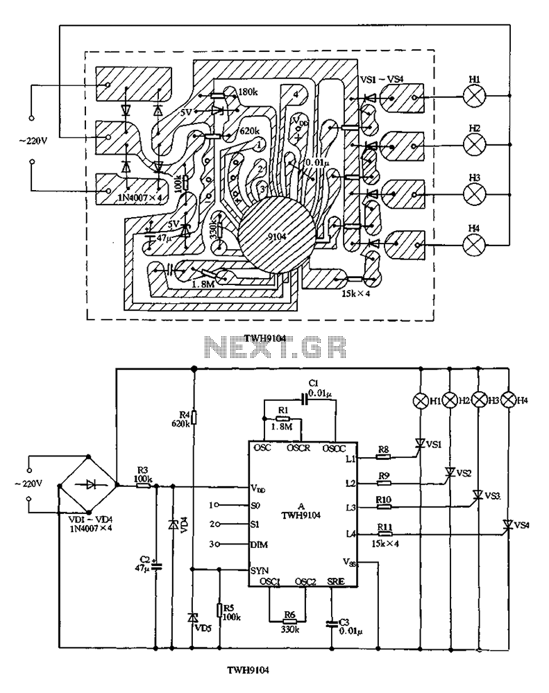
TWH9104 holiday lights ASIC
The circuit utilizes a VDI-VD4 bridge rectifier to convert 220V AC into a full-wave pulsating voltage, which powers lights H1 to H4. A buck regulator, composed of resistor R3 and diode VD4, reduces this voltage to approximately 5V DC, which...
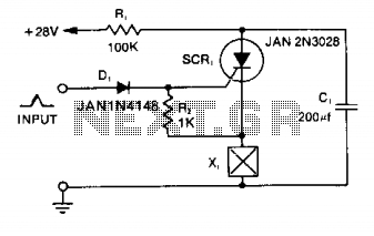
Squib-firing circuit
Capacitor C1 is charged to +28 V through resistor R1 and stores energy for firing the squib. A positive pulse of 1 mA applied to the gate of SCR1 will cause it to conduct, discharging C1 into the squib load...