


Thirty light water CNC circuit diagram CD4067 CD40193 NE555
#CD4067
#CD40193
#NE555
#lantern control
#water sports
#decorative lighting
#driver circuit
#30 outputs
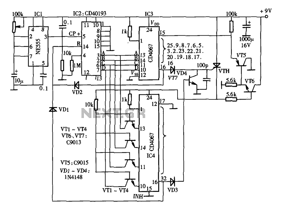
Description: The lantern control circuit allows for the management of 30 outputs through an external driver circuit, specifically designed for water sports or large decorative lantern applications. The circuit features a control pulse generator, which regulates the lights, and an output pulse divider circuit.
The lantern control circuit is designed to manage multiple lighting outputs effectively, making it suitable for applications in water sports and decorative displays. The integration of a control pulse generator allows for precise control over the lighting sequences and patterns, enhancing the visual effects during operation.
The external driver circuit interfaces with the lantern control circuit, enabling it to handle high-power outputs required for large lighting systems. This external driver ensures that the control circuit can manage the power demands of 30 individual outputs without compromising performance or safety.
The control pulse generator plays a crucial role in determining the timing and duration of the light outputs. By generating specific pulse signals, it can create various lighting effects such as blinking, fading, or steady illumination. This functionality is particularly useful in scenarios where dynamic lighting is desired, such as during water sports events or festive decorations.
Additionally, the output pulse divider circuit is integral to the overall operation of the lantern control circuit. It divides the control pulses generated by the pulse generator into appropriate signals for each output channel. This division allows for synchronized lighting effects across all outputs, ensuring that the lights operate cohesively.
Overall, the lantern control circuit is a sophisticated electronic system that combines multiple components to achieve flexible and powerful control over a large number of lighting outputs. Its design is tailored to meet the demands of both recreational and decorative lighting applications, providing a reliable solution for users seeking vibrant and engaging light displays. As shown in FIG lantern control circuit 30 outputs can be controlled by an external driver circuit 30 lights for water sports, as large decorative lantern controller circuit as shown in FIG. Circuit by the control pulse generator, control lights and control the output pulse divider circuit.
The lantern control circuit is designed to manage multiple lighting outputs effectively, making it suitable for applications in water sports and decorative displays. The integration of a control pulse generator allows for precise control over the lighting sequences and patterns, enhancing the visual effects during operation.
The external driver circuit interfaces with the lantern control circuit, enabling it to handle high-power outputs required for large lighting systems. This external driver ensures that the control circuit can manage the power demands of 30 individual outputs without compromising performance or safety.
The control pulse generator plays a crucial role in determining the timing and duration of the light outputs. By generating specific pulse signals, it can create various lighting effects such as blinking, fading, or steady illumination. This functionality is particularly useful in scenarios where dynamic lighting is desired, such as during water sports events or festive decorations.
Additionally, the output pulse divider circuit is integral to the overall operation of the lantern control circuit. It divides the control pulses generated by the pulse generator into appropriate signals for each output channel. This division allows for synchronized lighting effects across all outputs, ensuring that the lights operate cohesively.
Overall, the lantern control circuit is a sophisticated electronic system that combines multiple components to achieve flexible and powerful control over a large number of lighting outputs. Its design is tailored to meet the demands of both recreational and decorative lighting applications, providing a reliable solution for users seeking vibrant and engaging light displays. As shown in FIG lantern control circuit 30 outputs can be controlled by an external driver circuit 30 lights for water sports, as large decorative lantern controller circuit as shown in FIG. Circuit by the control pulse generator, control lights and control the output pulse divider circuit.
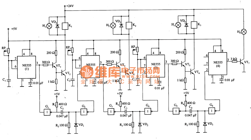
Sequence timer diagram composed by NE555
This is a sequence timer diagram composed of an NE555 timer. The timer can be set to any duration when the power is connected, allowing it to control an external system. In the circuit, K1-K3 are relays used to activate...
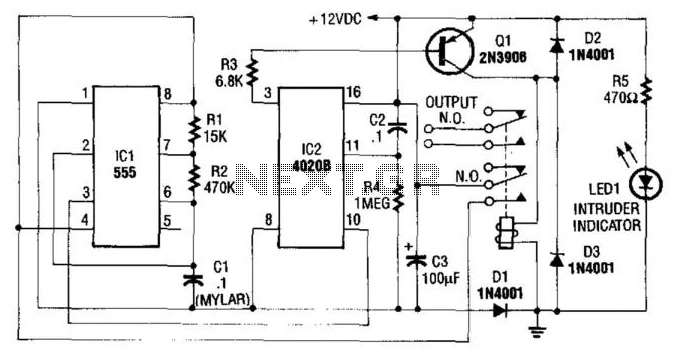
Auto Turn-Off Alarm With 8-Minute Delay
This circuit utilizes a NE555 timer and a CD4020B. When +12 Vdc is applied to the circuit, the output of IC2 is set low via C2, which activates the relay and IC1, functioning as a pulse generator. IC1 generates pulses...
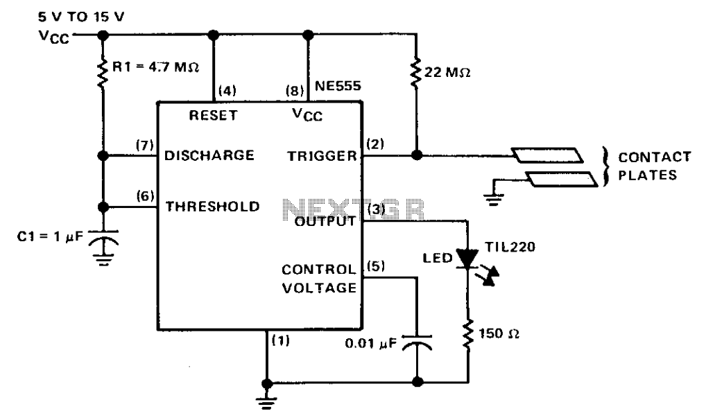
Touch switch
The circuit consists of a NE555 monostable timer, with a unique triggering method. The trigger input is held at a high voltage level by a 22-ohm resistor. When the contact plates are engaged, the operator's skin resistance decreases the total...
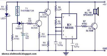
Simple fire alarm circuit using IC timer NE555
This is a simple smoke alarm circuit using a timer IC, the NE555. The circuit operates by illuminating a Light Dependent Resistor (LDR) with a lamp. When smoke obscures the light from the lamp, the resistance of the LDR changes,...
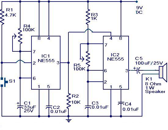
Doorbell circuit using NE555 IC
The primary component of this circuit is a doorbell utilizing two NE555 timer ICs. When the switch S1 is momentarily pressed, the speaker produces a bell sound, which is determined by the time period of the monostable multivibrator configured around...
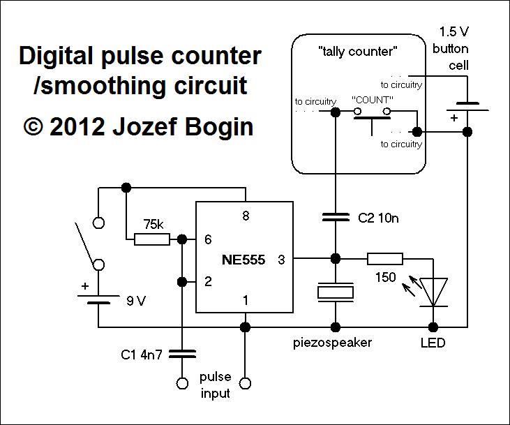
Digital pulse counter
This is a simple yet versatile pulse counting and smoothing integrator circuit featuring an NE555 timer as the waveform shaper and a small LCD display for output. Originally designed for counting pulses from Geiger counters, it includes a piezo speaker...
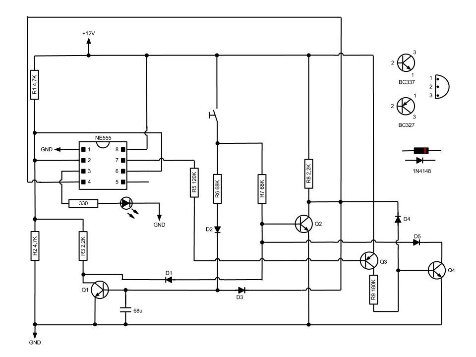
Simple Momentary Switch with 555
This circuit, based on the NE555 timer IC, toggles the output on and off using a momentary switch. It functions similarly to a mechanical latching relay but resets to its initial state when the power supply is turned off. This...
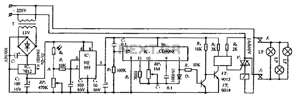
A house automatically fill light circuit
The circuit consists of three parts: a light control section, a time control section, and a power supply section. The light control section utilizes a photoresistor (Rg) and a variable resistor (RP) to detect light levels. During the day, when...
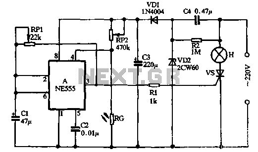
Flashing warning light produced by light control NE555 circuit
VDI, VD2, C3, and C4 form a simple half-wave rectifier capacitor step-down regulator circuit. This circuit can output approximately 12V DC voltage after power is applied across C3, which is utilized for the time base circuit. Additionally, the time base...