


With TWH9248 9249 an auto lighting
#TWH9248
#TWH9249
#auto lighting
#220V AC
#12V DC
#6V DC
#voltage regulator
#rectifier
#filter capacitor
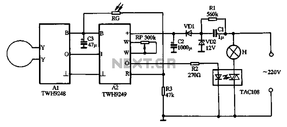
Description: The circuit operates on 220V AC input and utilizes a CL buck converter, a VDI rectifier, and a VD2 regulator along with a filter capacitor (C2) to provide a stable 12V DC output for module A2. Module A2 includes an internal 6V regulator that outputs a 6V DC voltage. A sensitive electrical resistor (RG) is connected across the gate control terminal of the TWH9249, which is linked to the 6V output terminal (B). The circuit features an automatic light control function that prevents operation during the day, keeping the lamp (H) off. At night, or in low light conditions, the circuit resumes normal operation. When a body moves within the detection range, the module detects microwave signals reflected from the body. The internal processing circuit generates a delay signal at terminal A2, activating the solid-state relay (TAC108) to turn on the lamp (H). If the human body remains motionless after the initial detection, the lamp will turn off after the delay signal. If movement is detected again, the lamp will remain lit. A potentiometer (RP) is included to adjust the sensitivity of the detection.
The described circuit is designed for automatic lighting control using a microwave detection system. The 220V AC input is first converted to a lower voltage using a CL buck converter, ensuring efficient power management. The VDI rectifier converts the AC voltage to DC, while the VD2 regulator stabilizes the output voltage to 12V DC, which powers the entire module A2. The filter capacitor (C2) smooths the output, ensuring stable voltage for sensitive components.
Module A2 incorporates an internal regulator that steps down the 12V to a 6V output, which is necessary for the operation of the TWH9249 gate control terminal. The sensitive resistor (RG) plays a critical role in controlling the gate of the TWH9249, allowing for the modulation of the signal based on the 6V output. This setup is essential for enabling the automatic light control feature.
The circuit's functionality is particularly notable during nighttime or low-light conditions when it detects movement. The microwave detection system works by emitting microwave signals and analyzing the echoes reflected back from any moving object, such as a human body. Upon detecting movement, the internal processing circuit at module A2 generates a delay signal that activates the solid-state relay (TAC108), which in turn powers the lamp (H). This provides immediate illumination in response to detected motion.
The delay mechanism ensures that the lamp does not turn off immediately after the motion ceases, allowing for a grace period during which the light remains on. This feature is designed to enhance user convenience, as it caters to brief movements without causing the lamp to flicker or turn off unexpectedly.
Furthermore, the inclusion of a potentiometer (RP) allows for fine-tuning of the detection sensitivity, enabling the user to adjust the system based on environmental conditions or specific requirements. This flexibility ensures that the circuit can be adapted for various applications, making it suitable for both residential and commercial lighting solutions. Overall, this circuit exemplifies a practical application of modern electronic design principles in creating an efficient and user-friendly automatic lighting system.220V AC by Cl buck, VDI rectifier, VD2 regulator and filter capacitor C2, output stable 12V DC voltage for use module A2, Al through internal A2 6V regulator outputs in 6V DC v oltage. Sensitive electrical resistor RG connected across TWH9249 gate control terminal R 6V voltage output terminal B, the circuit has an automatic light control function, the circuit will be blocked during the day does not work, H lamp is not lit, at night or when comparing light dark circuit that is able to lift the blockade restored to normal operation. When the body moves within the detection range, the module receives a microwave transmitter and the microwave echo reflected from the body compared to the more, the internal processing circuit by O terminal A2 output a delay signal to the solid state relay TAC108 turned on, the lamp H namely lit.
As the human body or human remains absolutely motionless after the departure, after the delay signal lamp goes out. If people move back, the lamp H will continue to light up. Circuit potentiometer RP can be used to adjust the detection sensitivity.
The described circuit is designed for automatic lighting control using a microwave detection system. The 220V AC input is first converted to a lower voltage using a CL buck converter, ensuring efficient power management. The VDI rectifier converts the AC voltage to DC, while the VD2 regulator stabilizes the output voltage to 12V DC, which powers the entire module A2. The filter capacitor (C2) smooths the output, ensuring stable voltage for sensitive components.
Module A2 incorporates an internal regulator that steps down the 12V to a 6V output, which is necessary for the operation of the TWH9249 gate control terminal. The sensitive resistor (RG) plays a critical role in controlling the gate of the TWH9249, allowing for the modulation of the signal based on the 6V output. This setup is essential for enabling the automatic light control feature.
The circuit's functionality is particularly notable during nighttime or low-light conditions when it detects movement. The microwave detection system works by emitting microwave signals and analyzing the echoes reflected back from any moving object, such as a human body. Upon detecting movement, the internal processing circuit at module A2 generates a delay signal that activates the solid-state relay (TAC108), which in turn powers the lamp (H). This provides immediate illumination in response to detected motion.
The delay mechanism ensures that the lamp does not turn off immediately after the motion ceases, allowing for a grace period during which the light remains on. This feature is designed to enhance user convenience, as it caters to brief movements without causing the lamp to flicker or turn off unexpectedly.
Furthermore, the inclusion of a potentiometer (RP) allows for fine-tuning of the detection sensitivity, enabling the user to adjust the system based on environmental conditions or specific requirements. This flexibility ensures that the circuit can be adapted for various applications, making it suitable for both residential and commercial lighting solutions. Overall, this circuit exemplifies a practical application of modern electronic design principles in creating an efficient and user-friendly automatic lighting system.220V AC by Cl buck, VDI rectifier, VD2 regulator and filter capacitor C2, output stable 12V DC voltage for use module A2, Al through internal A2 6V regulator outputs in 6V DC v oltage. Sensitive electrical resistor RG connected across TWH9249 gate control terminal R 6V voltage output terminal B, the circuit has an automatic light control function, the circuit will be blocked during the day does not work, H lamp is not lit, at night or when comparing light dark circuit that is able to lift the blockade restored to normal operation. When the body moves within the detection range, the module receives a microwave transmitter and the microwave echo reflected from the body compared to the more, the internal processing circuit by O terminal A2 output a delay signal to the solid state relay TAC108 turned on, the lamp H namely lit.
As the human body or human remains absolutely motionless after the departure, after the delay signal lamp goes out. If people move back, the lamp H will continue to light up. Circuit potentiometer RP can be used to adjust the detection sensitivity.
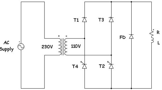
introduction to controlled rectifiers with converter
Controlled rectifiers are line-commutated AC to DC power converters that convert a fixed voltage and fixed frequency AC power supply into a variable DC output voltage. The input supply provided to a controlled rectifier is an AC supply with a...
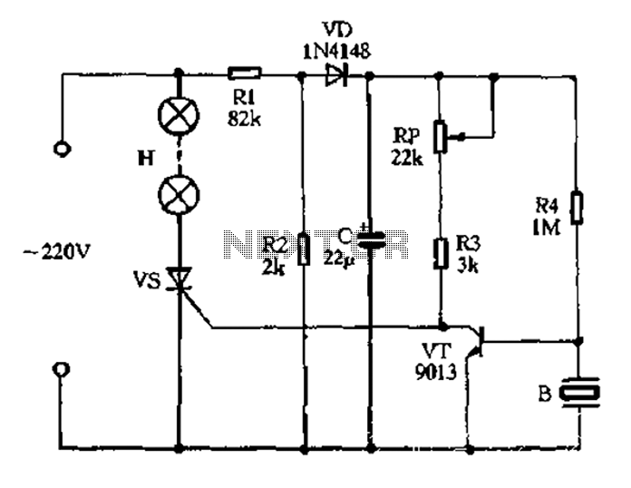
The easiest musical voice lights
The circuit operates on 220V AC, utilizing resistors R1 and R2 to create a partial voltage drop. A VD half-wave rectifier converts this AC voltage to approximately 3V DC across capacitor C. An adjustment potentiometer RP is incorporated to control...
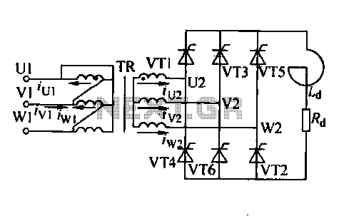
Three-phase controlled rectifier circuit
Trigger circuit routing forms include various types such as simple trigger circuits, single-junction transistor trigger circuits, synchronous sine wave trigger circuits, sawtooth transition phase shift (synchronous) trigger circuits, and integrated trigger circuits. This section presents individual cases for introduction due...
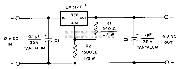
Hand-held-transceiver-dc-adapter
This adapter provides a regulated 9-V source for operating a Kenwood TR-2500 hand-held transceiver in a vehicle. The mounting tab of the LM317T is electrically connected to its output pin, which should be considered during the construction of the adapter....
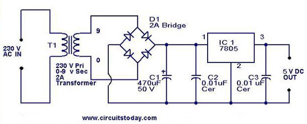
5V power supply using 7805 IC with circuit diagram
A 5V power supply using IC 7805 is designed and explained with a neat circuit diagram.
The circuit for a 5V power supply utilizing the IC 7805 voltage regulator is a straightforward and efficient design that provides a stable output voltage...

thrifty voltage regulator
One of the drawbacks of a three-pin voltage regulator is that the input voltage needs to be 2.5 to 3 V higher than the output voltage. This makes these integrated regulators unsuitable for battery power supplies. For instance, if the...
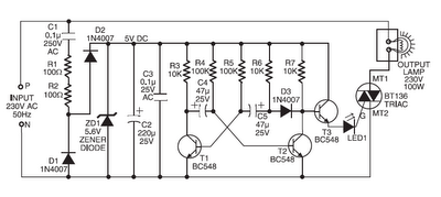
220v ac operated christmas light star
Components such as resistors R1 and R2, capacitors C1, C2, and C3, diodes D1 and D2, and a zener diode ZD1 are utilized to create a stable 5V DC supply voltage that delivers the necessary current to operate the multivibrator...
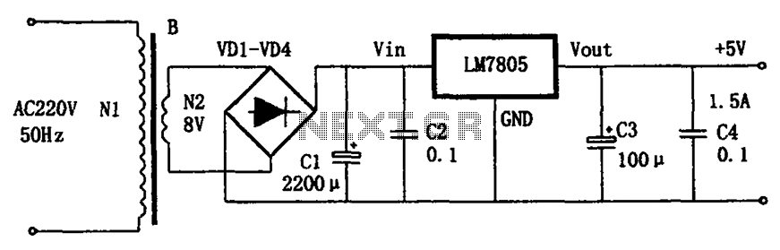
LM7805 + 5V power supply configuration
The circuit illustrated in the figure provides an output voltage of +5V and an output current of 1.5A. It comprises a power transformer, a bridge rectifier circuit consisting of diodes D1 to D4, and filter capacitor C1. Additionally, capacitors C2...
CF1 CF2 main circuit
AC voltage is rectified by a bridge (VD1-VD4). A resistor (R1) limits the buck, while diode (VD5) provides clipping. A trapezoidal wave is generated as the trigger circuit for DC voltage and synchronization. When the base of transistor (VT1) receives...