
marx generator

The device features a Marx generator with a ladder-like construction, where the capacitors are mounted horizontally on a grey PVC tube. Resistor chains are positioned vertically on each side of the capacitors. The spark gaps are formed by bent wires, while a vertical metal rod on the right serves as a ground connection. The charging system consists of a flyback transformer driving a TV cascade.
In the initial version, the spark gaps were made from approximately 1 mm diameter copper wire, bent into a ring of about 2 cm in diameter to minimize corona and premature breakdown. For optimal performance, all gaps should be uniformly spaced, although some suggest that the first gap should be slightly narrower. Adjustment is achieved by bending the wires until a rod or tube of suitable diameter can fit through. The improved version employs 1 cm diameter spherical nuts on M6 screws, allowing for easy and stable gap adjustments. The gaps are housed in a cable duct with a lid that can be opened or closed for visibility.
Each stage of the Marx generator is equipped with one spark gap mounted in the cable duct, connected to the capacitors. In the initial design, the charging resistors were composed of a series of four 2 kOhm, 2 Watt carbon film resistors. This relatively low resistance of 8 kOhm facilitated rapid charging and minimized voltage drop due to corona and leakage currents, but limited the output voltage pulse duration to approximately 30 µs, restricting the achievable spark length to around 30 cm. The resistors frequently failed, especially when the output was open, as they were operated well beyond their rated voltage.
The enhanced version incorporates two commercial high-voltage resistors (Vishay HGR0939, 1 MOhm, 5 kV) in series, significantly improving reliability and increasing the falling edge time constant to 8 ms. However, this change results in longer charging times and a reduced firing rate, with noticeable corona losses. The 10-stage Marx generator features improved spark gaps and 20 MOhm charging resistors, with the distance between the main discharge electrodes set at 40 cm. Given that the peak voltage is likely less than ten times the charging voltage (30 kV), this configuration approaches the maximum expected spark length for needle electrodes.
The maximum discharge length is influenced by the resistor values connecting each stage; larger resistor values allow for longer distances, up to an expected optimal limit. The operation principle suggests that once the gaps enter a conductive state, the capacitors begin discharging through the resistors while a spark develops at the output terminal. The duration of spark development increases with the distance to ground. If the capacitors discharge too quickly through the resistors, the spark may not fully develop. With the current values of resistance and capacitance, the characteristic time is 8 ms. Observations indicate that the discharge induces significant voltage transients in ground or mains leads, resulting in damage to components such as a burnt mains switch and a destroyed ground fault interrupter. Proper grounding is essential to mitigate these effects.One spark gap (in a first version these were just copper wires bent into a ring at the end to suppress corona, the current design is somewhat more sophisticated and uses spherical electrodes), It produces a 300kV output pulse with a discharge energy of 36 Joule. The discharge path is more than 40cm long and produces a loud bang - enough to make it uncomfortable to the ears.
Time exposure of several discharges of the marx generator. The ladder-like construction is the actual generator, the caps are mounted horizontally on the grey PVC tube. Vertically, left and right from the caps, are the resistor chains. The gaps are simply bent wires. The vertical metal rod to the right is grounded. The remaining stuff is the charging system, a flyback driving a TV cascade. Spark gaps: In a first version, the spark gaps were made of about 1mm diameter copper wire, which was bent into a ring (about 2cm diameter) to prevent corona and premature breakdown.
For optimal operation, all gaps should be equally wide. (Some say that the frist gap should be somewhat less wide, but for me it also works if they are all equal. Maybe this has some drawback that I have not yet noticed. ). Adjustment is done by slightly bending the wires until a rod or tube of suitable diameter just fits through.
The improved version makes use of 1cm diameter spherical nuts on M6 screws. The gaps are thus easily adjustable and should be stable at their position. The gaps are mounted into a cable duct with a lid which can be opened or closed, depending on whether you want the gaps visible or not. Schematic drawing of the improved spark gap. For each stage, one such gap is mounted in the cable duct. The whole structure is then attached to the marx generator and wired to the caps. Charging resistors: In the first version, the charging resistors consisted of a string of four 2kOhm 2Watt carbon film resistors each.
This relatively low resistance of 8KOhm allowed for rapid charging and low voltage drop due to corona and other leakage currents, but also caused the output voltage pulse to decay with a time constant of around 30us. The achievable spark length was thus limited by the short duration of the pulse to around 30cm. Also, the resistors were operated far beyond their design voltage (probably 500V) and frequently broke down, in particular when the output was accidentally "open", i.
e. a spark did not develop and the whole energy stored had to be dissipated by the resistors. The improved version uses two commercial high voltage resistors (Vishay HGR0939, 1MOhm, 5kV, bought via ebay) in series, resulting in much improved reliability and an increased falling edge time constant of 8ms. As a drawback, the charging time is also much longer and the "fire rate" lower, and corona losses are noticable now.
10-stage marx generator with improved spark gaps and 20MOhm charging resistors. The distance between the main discharge electrodes is 40cm. Taking into account that the actual peak voltage is probably less than 10x the charging voltage (30kV), this already comes close to the maximum spark length expected between needle electrodes. Observations: The maximum discharge length depends on the value of the resistors connecting each stage.
The larger this value, the longer the possible distance, up to some expected optimal value at least. Possible explanation: Once the gaps are in the conducting state, the caps begin to discharge through these resistors. At the same time, a spark starts to develop at the output terminal. This takes the longer the bigger the distance to ground is. If the caps discharge too quickly through the resistors, the spark has not enough time to fully develop.
With the current values of R and C, the characteristic time is 8ms. The discharge seems to induce huge voltage transients in ground and/or mains leads. This has resulted in a burnt mains switch and a destroyed ground fault interrupter. Grounding the 🔗 External reference
Related Circuits
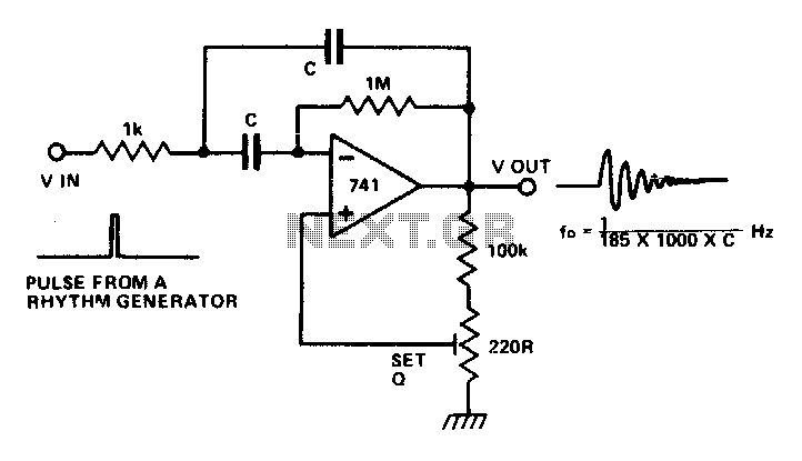
The circuit is a multiple feedback bandpass filter. A brief click (pulse) causes it to resonate at its natural frequency. The oscillations diminish exponentially, closely resembling various naturally occurring percussive or plucked sounds. The higher the quality factor (Q),...
This negative oxygen ion generator circuit consists of a full-wave dual voltage rectifier circuit, a pulse oscillation circuit, and a negative high voltage generation circuit, as illustrated in figure 9-116. The dual voltage rectifier circuit is constructed using diodes...
This type of design can produce a very high amperage current for a fraction of a second that can be used to do some useful work if properly harnessed. The switching device could be a rotating spark gap as...
In this circuit, a waveform generator is used as a stable voltage-controlled oscillator (VCO) in a Phase-Locked Loop (PLL). The circuit utilizes a waveform generator configured as a voltage-controlled oscillator (VCO), which is a critical component in the design of...
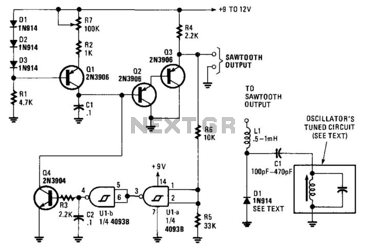
This circuit generates a linear sawtooth waveform with a frequency range from 30 Hz to 3,000 Hz. Q1 acts as a constant-current source that charges capacitor C1 until the output level at the emitter of Q3 triggers operational amplifiers...
This design outlines a simple 1 kHz square wave generator utilizing a few components and the LM3909 integrated circuit, which is beneficial for testing audio equipment. The circuit operates on a single 1.5V battery cell, producing a maximum output...