
Sawtooth Generator For Sweep Generators
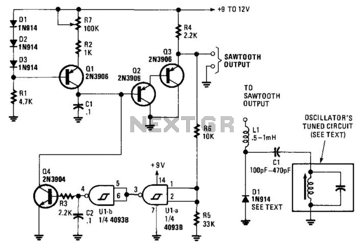
The described circuit utilizes a constant-current source, Q1, which is critical for maintaining a steady charging rate for capacitor C1. The charging process results in a linear voltage ramp across C1, which is essential for generating the sawtooth waveform. Once the voltage across C1 reaches a predetermined threshold, determined by the configuration of operational amplifiers U1A and U1B, a trigger signal is generated.
Operational amplifiers U1A and U1B are configured as a comparator circuit. When the voltage at the emitter of Q3 exceeds the reference voltage set by the feedback network within the op-amps, they output a high signal that turns on transistor Q4. The activation of Q4 provides a discharge path for C1, rapidly bringing its voltage back to zero and thereby resetting the cycle.
The frequency of the sawtooth waveform can be modified by adjusting the capacitance of C1. Increasing the capacitance will slow down the charging process, resulting in a lower frequency output, while decreasing the capacitance will increase the frequency. The circuit's design allows it to operate effectively across a wide range of frequencies, making it suitable for applications requiring variable frequency waveform generation.
In practical implementations, care must be taken to ensure that the components, particularly Q1, Q3, and Q4, are selected to handle the desired frequency range and load conditions. Additionally, power supply considerations for the operational amplifiers and transistors will influence the overall performance and stability of the circuit. Proper layout and decoupling techniques should also be employed to minimize noise and ensure reliable operation across the specified frequency range. This circuit will generate a linear sawtooth between 30 Hz and 3 000 Hz. Ql is a constant-current s ource that charges CI until the output level at Q3 emitter triggers U1A and U1B, which turns on Q4 and discharges CI. The frequency range can be varied by changing the value of CI. This circuit should be good to several tens of kHz. 🔗 External reference
Related Circuits
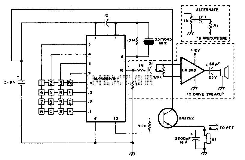
The circuit requires a minimum number of components and utilizes a low-cost standard 379.545 MHz television color-burst crystal. The speaker can be omitted, allowing the output to be directly connected to the microphone input of a transmitter. The circuit design...
There are two main types of oscillators: the most common is the Wein Bridge oscillator variety, which has low distortion but offers only sine wave output and can suffer from amplitude bounce as frequency changes. The second type, which...
A high voltage power supply DC converter that operates between 3V to 500V has been suggested for use with Geiger tubes. However, during simulation, the output remained at nearly 9V, which matches the input voltage. The schematic drawn has...
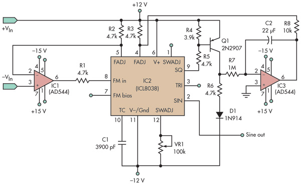
This basic voltage-controlled oscillator (VCO) and waveform generator integrated circuit (IC) circuit features a voltage follower loop (formed with IC1) and a symmetry feedback loop (IC3) designed to eliminate asymmetric duty cycles that can lead to distortion at low...
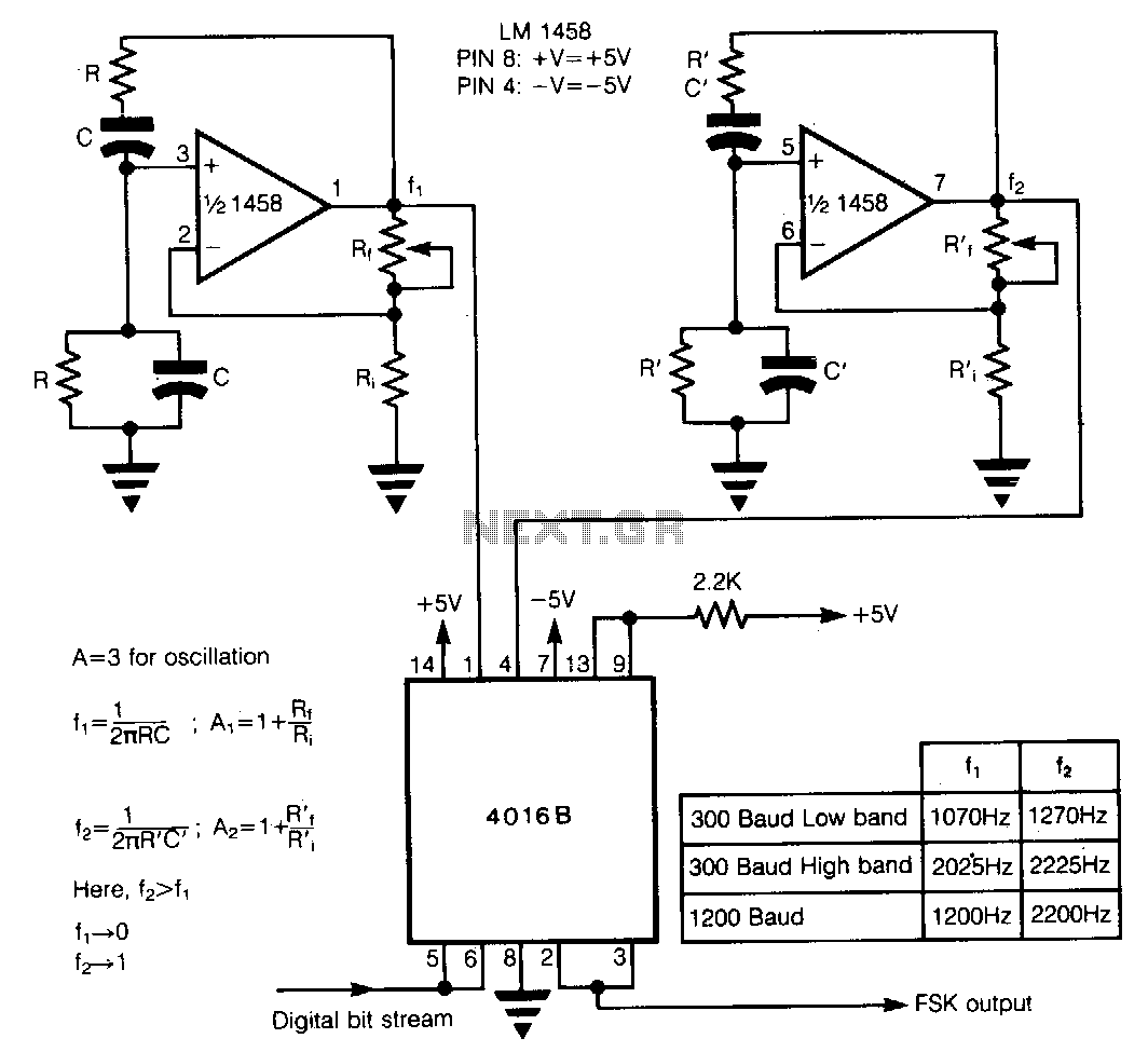
In Frequency Shift Keying (FSK), two distinct frequencies are utilized to represent the binary digits 0 and 1. The core of the circuit comprises two Wien-bridge oscillators constructed with a dual operational amplifier LM1458, each generating one of the...
An audio frequency signal generator can output audio signals, 465 kHz spectral amplitude signals, and 52.5 Hz to 16 kHz high-frequency amplitude-modulated signals. The high-frequency oscillator's vibration frequency is determined by the components G and L. A variety of...