


0 to 10V output multiplexer measuring circuit
#multiplexer
#low drift
#voltage output
#resistive load
#bridge excitation
#high linearity
#precision measurement
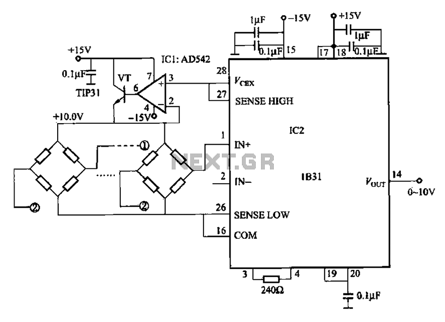
Description: The 1832 low drift input has a temperature coefficient of 0.07 µV/°C (RTI, G 500) and exhibits excellent linearity with a maximum deviation of 0.005%. It can drive resistive loads greater than 120 ohms in a bridge excitation circuit, with an output range of +4 to +15 V. The circuit includes an oscillator and filter, with an output drift of only 40 ppm/°C for precision bridge transducer signal conditioning. Additionally, it features two fixed gain settings of 333.3 and 500, with adjustable gain pins ranging from 100 to 5000. The output voltage is 10 V, and the operating supply voltage range is from 12 to 18 V.
The 1832 low drift input circuit is designed for high-precision applications where minimal temperature drift and excellent linearity are critical. The temperature coefficient of 0.07 µV/°C ensures that the output remains stable across varying temperature conditions, making it suitable for sensitive transducer applications. The linearity specification of 0.005% maximum indicates that the output signal closely follows the input signal without significant distortion, which is essential for accurate measurements.
The circuit's capability to drive resistive loads greater than 120 ohms is particularly important for bridge excitation applications, where the sensor's output must be sufficiently strong to provide reliable data. The output voltage range of +4 to +15 V allows for flexibility in interfacing with various transducer types, while the built-in oscillator and filter enhance signal integrity by reducing noise and unwanted frequency components.
The output drift of only 40 ppm/°C is indicative of the circuit's high stability, which is vital for precision signal conditioning in bridge transducer systems. The inclusion of two fixed gain settings (333.3 and 500) along with adjustable gain pins provides versatility in scaling the output signal to match the requirements of different applications, accommodating a wide range of input signal amplitudes from 100 to 5000.
The specified output voltage of 10 V is optimal for many data acquisition systems, ensuring compatibility with standard analog input ranges. The operating supply voltage range of 12 to 18 V allows for integration with various power supply configurations, making the 1832 low drift input circuit a robust choice for engineers designing high-performance measurement systems.1832 low drift input 0. 07pr, V/oC (RTI, G 500), excellent linearity (maximum 0.005%), can drive resistive loads greater than 120fl bridge excitation circuit (output + 4 ~ + 15 V) with osc, filter circuit, output drift only precision bridge transducer signal conditioning circuit 40ppm/of. At the same time, also set up 333.3,500 two fixed gain 100 to 5000 pins and gain adjustment pins. Output voltage is 10V. Operating supply voltage range of (12 ~ 18) V.
The 1832 low drift input circuit is designed for high-precision applications where minimal temperature drift and excellent linearity are critical. The temperature coefficient of 0.07 µV/°C ensures that the output remains stable across varying temperature conditions, making it suitable for sensitive transducer applications. The linearity specification of 0.005% maximum indicates that the output signal closely follows the input signal without significant distortion, which is essential for accurate measurements.
The circuit's capability to drive resistive loads greater than 120 ohms is particularly important for bridge excitation applications, where the sensor's output must be sufficiently strong to provide reliable data. The output voltage range of +4 to +15 V allows for flexibility in interfacing with various transducer types, while the built-in oscillator and filter enhance signal integrity by reducing noise and unwanted frequency components.
The output drift of only 40 ppm/°C is indicative of the circuit's high stability, which is vital for precision signal conditioning in bridge transducer systems. The inclusion of two fixed gain settings (333.3 and 500) along with adjustable gain pins provides versatility in scaling the output signal to match the requirements of different applications, accommodating a wide range of input signal amplitudes from 100 to 5000.
The specified output voltage of 10 V is optimal for many data acquisition systems, ensuring compatibility with standard analog input ranges. The operating supply voltage range of 12 to 18 V allows for integration with various power supply configurations, making the 1832 low drift input circuit a robust choice for engineers designing high-performance measurement systems.1832 low drift input 0. 07pr, V/oC (RTI, G 500), excellent linearity (maximum 0.005%), can drive resistive loads greater than 120fl bridge excitation circuit (output + 4 ~ + 15 V) with osc, filter circuit, output drift only precision bridge transducer signal conditioning circuit 40ppm/of. At the same time, also set up 333.3,500 two fixed gain 100 to 5000 pins and gain adjustment pins. Output voltage is 10V. Operating supply voltage range of (12 ~ 18) V.
TIPE Project
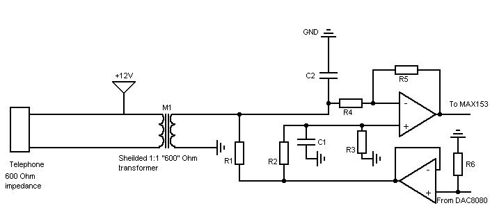
A simple non-commercial grade multiplexer compatible with telephones. It will support four telephone lines and will multiplex over one cable. The topic was free of choice but had to be oriented around the theme of "PrG©vision" (prediction). As anticipated, the...
INVERTER_AND_PULSE_STRETCHER
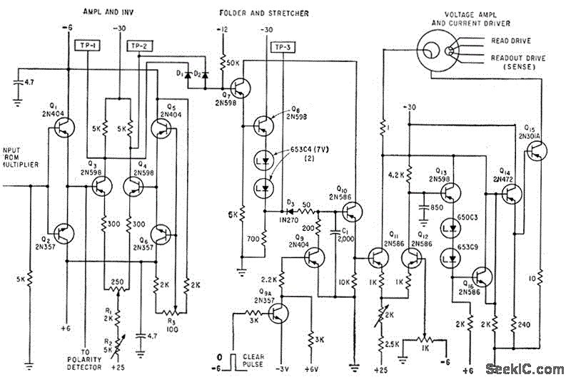
The circuit samples the output of a multiplexer and provides the necessary current for driving a transfluxor in an analog-to-digital converter that generates a six-bit binary Gray code. -N. Aron and C. Granger, Analog-To-Digital Converter Uses Transfluxors, Electronics, 35:20, p...
2-to-1 Multiplexer
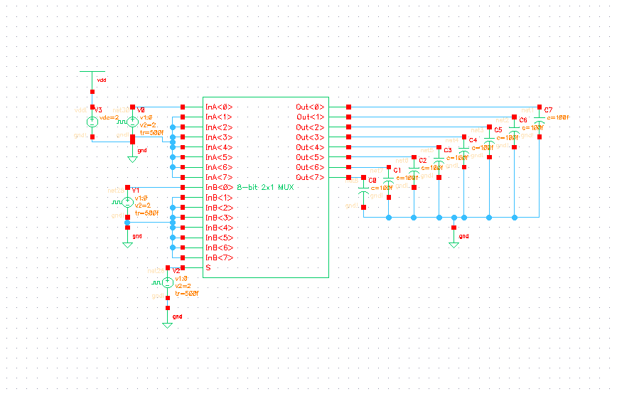
The 8-bit 2x1 multiplexer comprises 16 tristate buffers and a static inverter. It is configured such that when the select bit is low, 8 of the input bits are transmitted through the tristate buffers to the 8 output bits. Conversely,...
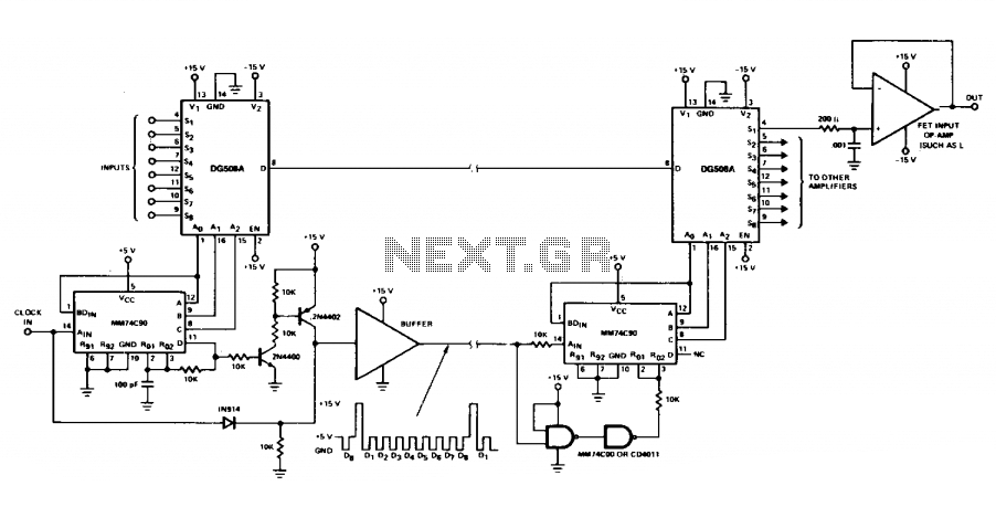
Mux-Demux system
Multiple signals can be transmitted between two locations at the same time by making a minor adjustment to the receiver circuit. An additional DG508A is employed as a demultiplexer, enabling continuous monitoring of all 8 channels.
To implement a system for...
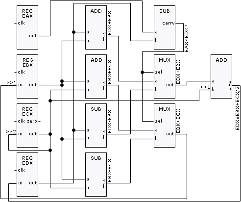
clock-synchronised multiplexers
This is the second part of the square root algorithm. It was developed during the final stages of finishing this website and reviewing this document for publication. While Part I focused on an empirical discovery for a sequential algorithm to...
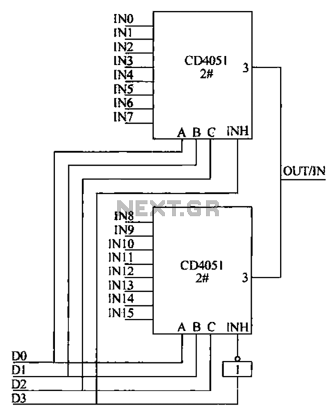
Analog multiplexer CD4051 extension circuit 1
The CD4051 is a single-ended input 8-channel multiplexer that features three channel select inputs (A, B, C) and an inhibit input (INH). The signals at inputs A, B, and C are utilized to control the selection of one of the...
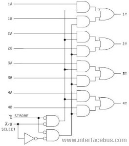
IC Multiplexers
There is a lack of clarity regarding the difference between a data selector and a multiplexer. The designs previously engaged in ceased utilizing small-scale integrated circuits in the early 1990s, as the physical aspect transitioned to general-purpose programmable array logic...
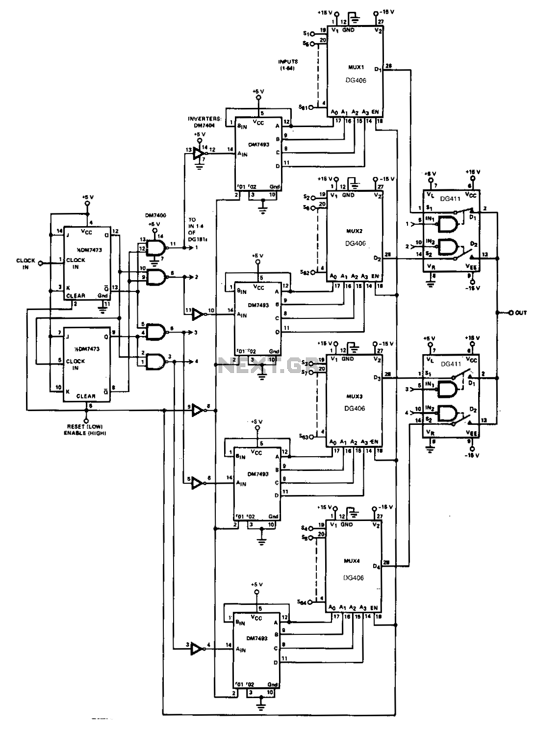
Two-level-multiplexer
When a large number of channels are multiplexed, the outputs of two or more multiplexers can be connected together, and each multiplexer can be enabled sequentially. In the inhibit mode, the multiplexer consumes less power, and its output and inputs...
INVERTER_AND_PULSE_STRETCHER
The circuit samples the output of a multiplexer and provides the necessary current for driving a transfluxor in an analog-to-digital converter that generates a six-bit binary Gray code. -N. Aron and C. Granger, Analog-To-Digital Converter Uses Transfluxors, Electronics, 35:20, p...