


Clamp-on-current probe compensator
#current probe
#oscilloscope
#low-frequency response
#op amp
#feedback
#attenuation
#compensator
#Tektronix P6021
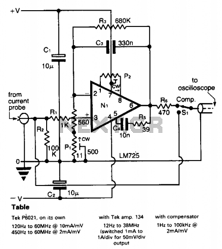
Description: A clamp-on current probe, such as the Tektronix P6021, is an effective tool for displaying current waveforms on an oscilloscope. However, its low-frequency response is somewhat limited, as indicated in the accompanying table. The more sensitive range of the P6021 is 2 mA/mV, but it experiences a roll-off of 6 dB per octave below 450 Hz. A compensator is employed to counteract this low-frequency attenuation, utilizing components C3 and R4 along with PI in the feedback loop of operational amplifier N1. The operational amplifier used is a low-noise type, such as the LM725; however, it is necessary to limit the gain increase at lower frequencies to prevent amplifier noise and drift from overwhelming the signal. The values specified for C3 and R3 establish a lower frequency limit of less than 1 Hz. A test square wave of ±10 mA is applied to the current probe, allowing for the adjustment of PI to achieve minimal droop or overshoot in the output waveform. At higher frequencies, the response begins to decline starting at 100 kHz.
The clamp-on current probe configuration incorporates several key components designed to optimize performance across a range of frequencies. The operational amplifier N1 serves as the core of the signal processing unit, where its low-noise characteristics are critical for maintaining signal integrity. The feedback network, including C3 and R4, is strategically designed to enhance low-frequency response, effectively compensating for the inherent roll-off of the probe.
The choice of a low-noise operational amplifier like the LM725 is essential in applications where signal fidelity is paramount. To manage gain effectively, the circuit employs a feedback mechanism that adjusts the gain dynamically based on frequency. The values of C3 and R3 are crucial in defining the cutoff frequency, ensuring that the system remains responsive even at low frequencies while minimizing noise contributions.
The test square wave input of ±10 mA is a practical method for calibrating the probe's response. By observing the output waveform, adjustments can be made to the compensator PI to optimize the phase and amplitude characteristics, ensuring that the output remains stable without excessive droop or overshoot. This adjustment process is vital for achieving accurate readings when monitoring current waveforms.
At higher frequencies, the design anticipates a natural decline in response, commencing at 100 kHz. This characteristic is typical in many analog circuits and must be considered when selecting the probe for high-frequency applications. Overall, the integration of these components and their careful selection allows the Tektronix P6021 clamp-on current probe to function effectively across a wide frequency range, making it a valuable tool for electronic measurements.A clamp-on "current probe" such as the Tektronix P6021 is a useful means of displaying current waveforms on an oscilloscope. Unfortunately, the low-frequency response is somewhat limited, as shown in the Table. The more sensitive range on the P6021 is 2 mA/mV, but it has a roll-off of 6 dB per octave below 450 Hz.
The compensator counteracts the low-frequency attenuation, and this is achieved by means of C3 and R4 + PI in the feedback around op amp Nl. The latter is a low-noise type, such as the LM725 shown, and even so it is necessary at some point to limit the increasing gain with decreasing frequency; otherwise amplifier noise and drift will overcome the signal. The values shown for C3R3 give a lower limit below 1 Hz. A test square wave of ± 10 mA is fed to the current probe so that PI can be adjusted for minimum droop or overshoot in the output waveform.
At high frequencies, the response begins to fall off at 100 kHz.
The clamp-on current probe configuration incorporates several key components designed to optimize performance across a range of frequencies. The operational amplifier N1 serves as the core of the signal processing unit, where its low-noise characteristics are critical for maintaining signal integrity. The feedback network, including C3 and R4, is strategically designed to enhance low-frequency response, effectively compensating for the inherent roll-off of the probe.
The choice of a low-noise operational amplifier like the LM725 is essential in applications where signal fidelity is paramount. To manage gain effectively, the circuit employs a feedback mechanism that adjusts the gain dynamically based on frequency. The values of C3 and R3 are crucial in defining the cutoff frequency, ensuring that the system remains responsive even at low frequencies while minimizing noise contributions.
The test square wave input of ±10 mA is a practical method for calibrating the probe's response. By observing the output waveform, adjustments can be made to the compensator PI to optimize the phase and amplitude characteristics, ensuring that the output remains stable without excessive droop or overshoot. This adjustment process is vital for achieving accurate readings when monitoring current waveforms.
At higher frequencies, the design anticipates a natural decline in response, commencing at 100 kHz. This characteristic is typical in many analog circuits and must be considered when selecting the probe for high-frequency applications. Overall, the integration of these components and their careful selection allows the Tektronix P6021 clamp-on current probe to function effectively across a wide frequency range, making it a valuable tool for electronic measurements.A clamp-on "current probe" such as the Tektronix P6021 is a useful means of displaying current waveforms on an oscilloscope. Unfortunately, the low-frequency response is somewhat limited, as shown in the Table. The more sensitive range on the P6021 is 2 mA/mV, but it has a roll-off of 6 dB per octave below 450 Hz.
The compensator counteracts the low-frequency attenuation, and this is achieved by means of C3 and R4 + PI in the feedback around op amp Nl. The latter is a low-noise type, such as the LM725 shown, and even so it is necessary at some point to limit the increasing gain with decreasing frequency; otherwise amplifier noise and drift will overcome the signal. The values shown for C3R3 give a lower limit below 1 Hz. A test square wave of ± 10 mA is fed to the current probe so that PI can be adjusted for minimum droop or overshoot in the output waveform.
At high frequencies, the response begins to fall off at 100 kHz.
Versatile Op Amps Need No Resistors
One of the challenges faced by power supply designers today is the need to create a switching power supply that can function across various power systems in international markets. Forward mode switching power supplies typically operate within a limited voltage...
Op amp F003 composition of automatic exposure timer circuit
The F003 circuit is a versatile photographic component that functions as an operational amplifier amplifying automatic timer circuit. The operational amplifier A1 serves as an integrator, while operational amplifier A2 is configured as a comparator. A 2CR silicon photocell generates...

pic based oscilloscope clock
For those unfamiliar with electronics, it is important to understand that an oscilloscope essentially has a single timebase that moves the spot horizontally from left to right with consistent intensity. The vertical deviation corresponds to the input voltage. It becomes...
OSCILLOSCOPE COUNTER PREAMPLIFIER
The circuit provides a voltage gain of 20 ±0.1 dB within a frequency range of 500 kHz to 50 MHz. The low-frequency response of the amplifier can be enhanced by increasing the value of the 0.05 µF capacitor connected in...
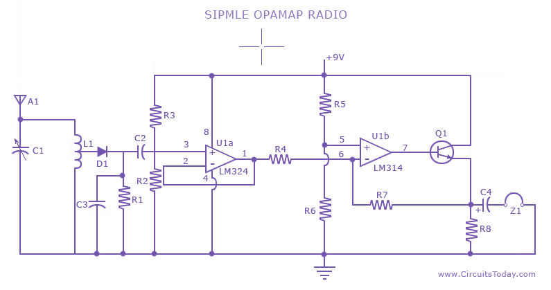
Simple Radio Circuit using Op Amp
A low-cost, simple radio circuit schematic using an operational amplifier. This radio circuit diagram consists of a sensitive audio amplifier that receives strong signals.
The presented radio circuit schematic utilizes an operational amplifier (op-amp) to create a cost-effective and straightforward radio...
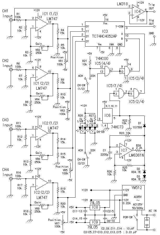
Oscilloscope 4 Channel Adapter
The method goes by the switching method. Making it be possible to see four kinds of the input signals at the same time by switching them at the short period. In addition to the way of introducing here, there is...
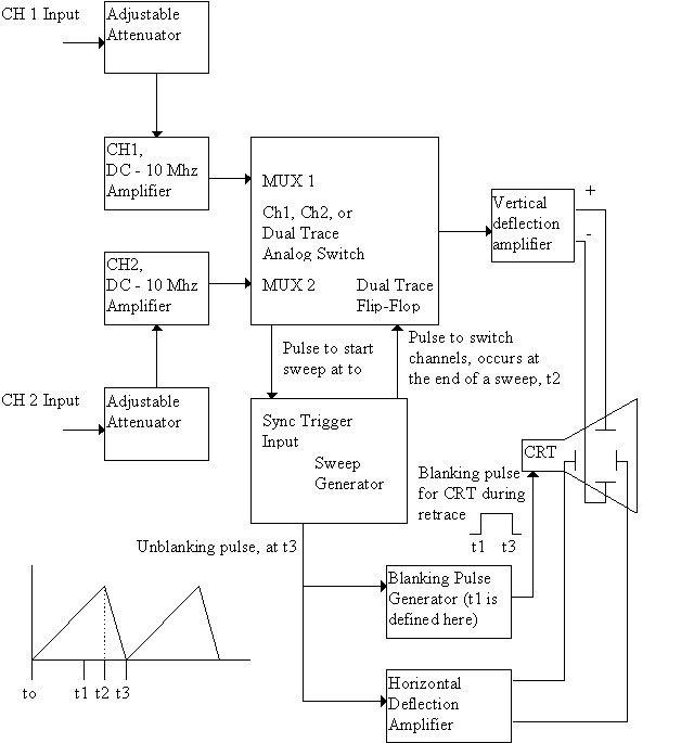
Dual-trace, triggered oscilloscope
This site contains public-domain schematics for a dual-trace, triggered oscilloscope, and some theory. Click on the topic in the table below to see the schematic for that block. I designed and built this oscilloscope in 1986 using the chassis of...
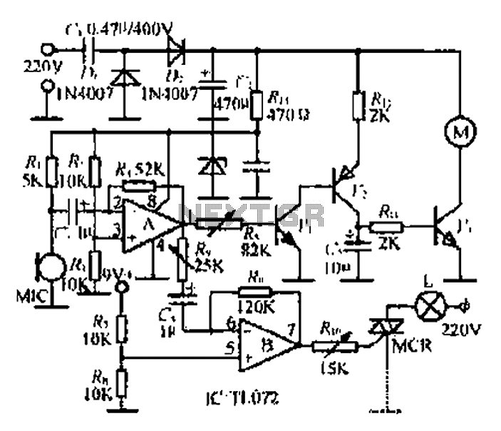
An electronic music rotating lights circuit
A microphone (MIC) is used to capture sound, which is then converted into a voltage signal. An operational amplifier (op-amp A) acts as a buffer; one output is directed to a motor drive circuit to control the motor's rotation in...
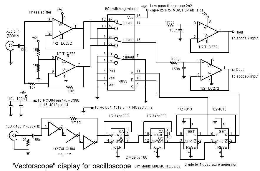
Phase indication by vectorscope
An oscilloscope capable of displaying in X/Y mode and a reference "LO" signal source are required. In-phase and quadrature reference square wave signals are generated using a divide-by-4, 2-bit ring counter with two D-type flip-flops. To utilize an RF generator...