


Evaluation Board For Single Supply 12-bit 500 Ksps Adc
#evaluation board
#ADC
#12-bit
#500 Ksps
#single supply
#data acquisition
#DDS
#direct digital synthesizer
#phase modulation
#frequency modulation
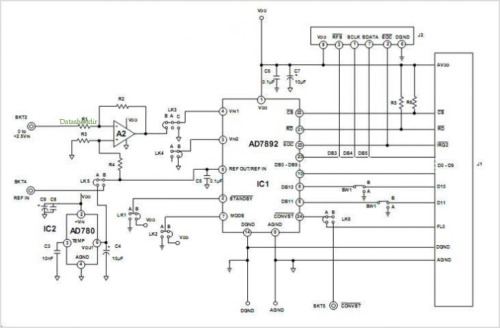
Description: This data sheet describes the evaluation board for the AD9834 direct digital synthesizer (DDS). The AD9834 is a numerically controlled oscillator that utilizes a phase accumulator, a sine look-up table, and a 10-bit DAC. The AD9834 can operate with clock frequencies up to 75 MHz. Both phase modulation and frequency modulation can be performed with the AD9834. Complete specifications for the AD9834 are available in the AD9834 data sheet and should be consulted alongside this data sheet when using the evaluation board. The evaluation board interfaces with the parallel port of a PC. Software is provided with the evaluation board that allows the user to easily program the AD9834. The AD9834 evaluation board includes a 75 MHz oscillator that provides the MCLK for the AD9834. This oscillator can be removed if necessary, allowing the AD9834 to be driven by a different clock oscillator or an external clock source via a BNC connector. A digital buffer is also present on the board to buffer signals from the edge connector.
The AD9834 evaluation board is designed to facilitate the testing and development of applications using the AD9834 direct digital synthesizer. The board incorporates essential components that enable users to explore the capabilities of the AD9834, which is notable for its ability to generate precise frequency outputs through digital control. The phase accumulator within the AD9834 allows for fine-tuning of the output waveform, while the sine look-up table ensures high fidelity in the generated waveforms.
Operating at clock frequencies of up to 75 MHz, the AD9834 can produce various modulation schemes, including both phase and frequency modulation. This versatility makes it suitable for a wide range of applications in communications and signal processing. The evaluation board connects to a PC's parallel port, providing a straightforward interface for programming and controlling the synthesizer.
Included software simplifies the programming process for the AD9834, allowing users to easily configure output frequencies and modulation parameters. The onboard 75 MHz oscillator generates the necessary master clock (MCLK) for the AD9834, ensuring it operates within its specified performance envelope. However, should the application require different clocking conditions, the onboard oscillator can be bypassed, enabling the connection of alternative clock sources through a BNC connector. This flexibility is advantageous for users who may need to integrate the AD9834 into more complex systems or require specific timing configurations.
Furthermore, the presence of a digital buffer on the evaluation board enhances signal integrity by ensuring that the signals from the edge connector are adequately buffered, minimizing signal degradation and enabling reliable operation. Overall, the AD9834 evaluation board serves as a comprehensive platform for evaluating the performance of the AD9834 DDS, providing users with the tools necessary to develop and optimize their applications effectively.This data sheet describes the evaluation board for the AD9834 direct digital synthesizer (DDS). The AD9834 is a numerically controlled Oscillator using a phase accumulator, a sine look-up table, and a 10-bit DAC The AD9834 CAN be operated with Clock frequencies up to 75 MHz. Both phase modulation and frequency modulation CAN be perfor med with the AD9834. Complete specifications for the AD9834 are available in the AD9834 data sheet and should be consulted in conjunction with this data sheet when using the evaluation board. The evaluation board Interfaces to the parallel port of a PC. Software is available with the evaluation board that allows the user to easily program the AD9834. The AD9834 evaluation board includes a 75 MHz Oscillator that provides the MCLK for the AD9834. The user CAN remove this Oscillator if required, and drive the AD9834 with a different Clock Oscillator or an external Clock source via a BNC connector.
A digital Buffer is also on the board so that the signals from the edge connector are buffered.
The AD9834 evaluation board is designed to facilitate the testing and development of applications using the AD9834 direct digital synthesizer. The board incorporates essential components that enable users to explore the capabilities of the AD9834, which is notable for its ability to generate precise frequency outputs through digital control. The phase accumulator within the AD9834 allows for fine-tuning of the output waveform, while the sine look-up table ensures high fidelity in the generated waveforms.
Operating at clock frequencies of up to 75 MHz, the AD9834 can produce various modulation schemes, including both phase and frequency modulation. This versatility makes it suitable for a wide range of applications in communications and signal processing. The evaluation board connects to a PC's parallel port, providing a straightforward interface for programming and controlling the synthesizer.
Included software simplifies the programming process for the AD9834, allowing users to easily configure output frequencies and modulation parameters. The onboard 75 MHz oscillator generates the necessary master clock (MCLK) for the AD9834, ensuring it operates within its specified performance envelope. However, should the application require different clocking conditions, the onboard oscillator can be bypassed, enabling the connection of alternative clock sources through a BNC connector. This flexibility is advantageous for users who may need to integrate the AD9834 into more complex systems or require specific timing configurations.
Furthermore, the presence of a digital buffer on the evaluation board enhances signal integrity by ensuring that the signals from the edge connector are adequately buffered, minimizing signal degradation and enabling reliable operation. Overall, the AD9834 evaluation board serves as a comprehensive platform for evaluating the performance of the AD9834 DDS, providing users with the tools necessary to develop and optimize their applications effectively.This data sheet describes the evaluation board for the AD9834 direct digital synthesizer (DDS). The AD9834 is a numerically controlled Oscillator using a phase accumulator, a sine look-up table, and a 10-bit DAC The AD9834 CAN be operated with Clock frequencies up to 75 MHz. Both phase modulation and frequency modulation CAN be perfor med with the AD9834. Complete specifications for the AD9834 are available in the AD9834 data sheet and should be consulted in conjunction with this data sheet when using the evaluation board. The evaluation board Interfaces to the parallel port of a PC. Software is available with the evaluation board that allows the user to easily program the AD9834. The AD9834 evaluation board includes a 75 MHz Oscillator that provides the MCLK for the AD9834. The user CAN remove this Oscillator if required, and drive the AD9834 with a different Clock Oscillator or an external Clock source via a BNC connector.
A digital Buffer is also on the board so that the signals from the edge connector are buffered.
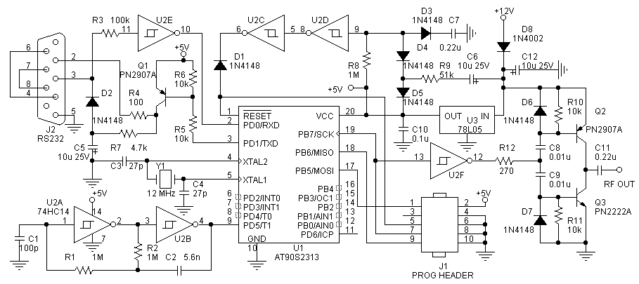
ZL1BPU exciter
Direct Digital Synthesis (DDS) frequency generation has been established for some time; however, many homebrew DDS projects tend to be complex and utilize costly chipsets. Murray's exciter requires only three inexpensive integrated circuits (ICs), and the entire assembly can be...
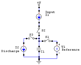
Dual-Slope Integrating ADC
A column-parallel analog-to-digital converter (ADC) has been developed for integration with CMOS active pixel sensors (APS). The design objectives focused on simplicity, compactness, moderate speed (greater than 10 kHz), current input, and acceptable accuracy (6 bits). The ADC is intended...
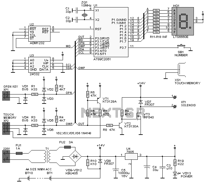
Analog to Digital Conversion
The project involves implementing analog-to-digital conversion using the ADC0804LCN 8-bit A/D converter. A circuit will be designed and programmed so that when an analog signal is input, the corresponding digital voltage is displayed on an LCD. Essentially, the circuit will...
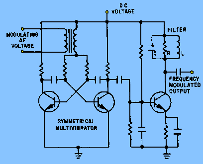
Methods of frequency modulation
The circuit depicted in figure 2-6 and discussed in previous sections serves illustrative purposes only and is not practical in real-world applications. Nevertheless, the fundamental principle involved—the variation in reactance of an oscillator circuit in response to modulating voltage—represents one...
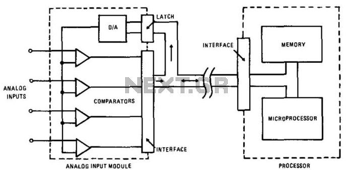
Data Acquisition System Ii
In this circuit, an HA-4900 series comparator is utilized alongside a digital-to-analog (D/A) converter to create a versatile, multichannel analog input for a data acquisition system. The processor first transmits an address to the D/A converter, after which it reads...
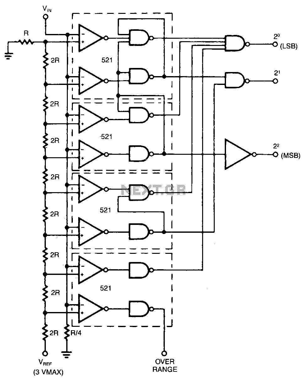
Adc
The conversion speed of this design is the sum of the delay through the comparator and the decoding gates. Reference voltages for each bit are developed from a precision resistor ladder network. Values of R and 2R are chosen so...
Dynamic Testing of High-Speed ADCs Part 2
The following article is a continuation of the application note titled "Defining and Testing Dynamic Parameters in High-Speed ADCs, Part 1." It outlines the test conditions and setup recommendations necessary for effectively measuring the dynamic performance parameters of high-speed analog-to-digital...
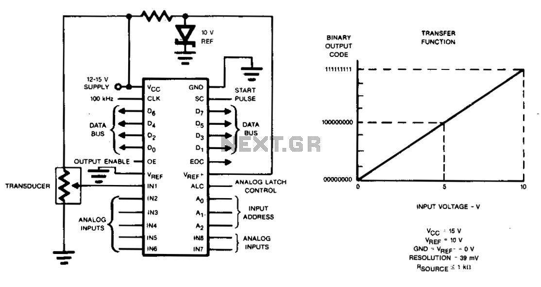
Data acquisition system
Charge redistribution is utilized to achieve analog-to-digital (A/D) conversion. In standard applications, this operates as a ratiometric conversion system for a microprocessor, where V^p is connected to ground and VREF+ is connected to Vcc. The output will provide a straightforward...
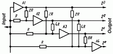
Simple Analog to Digital Converter
The simplest Analog to Digital Converter (ADC) can be constructed as shown in Figure 1. The input voltage, which can range from zero up to the power supply voltage (Vcc), is converted to a parallel binary code at the outputs...