


Intelligent digital voltmeter circuit HI7159A and 8031
#digital voltmeter
#HI7159A
#8031
#integrator
#BIMOS
#high accuracy
#5 1/2 bit
#low noise
#precision measurement
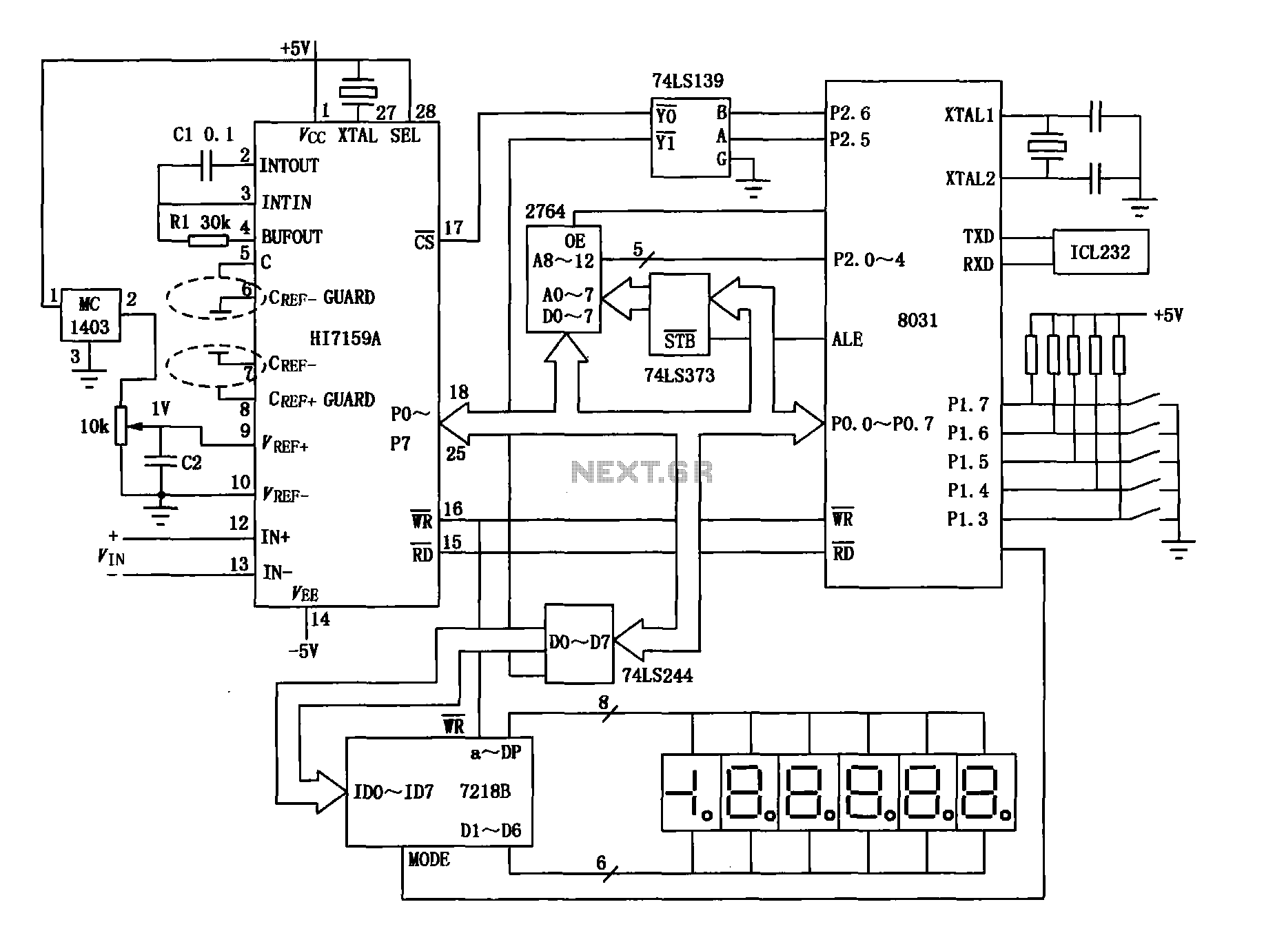
Description: An intelligent digital voltmeter circuit utilizing the HI7159A, 8031 microcontroller, and various other components as illustrated in the figure. The internal circuit incorporates a successive cumulative integrator, digital zero function, low noise BIMOS technology, and other advanced features. In 5 1/2 bit mode, the maximum count value is 199999, with an accuracy of 0.005%.
The intelligent digital voltmeter circuit is designed to provide precise voltage measurements with high accuracy. The core component, the HI7159A, is a specialized analog-to-digital converter (ADC) that enables the conversion of analog voltage signals into digital format. This ADC operates in conjunction with the 8031 microcontroller, which manages the processing and display of the measured values.
The circuit employs a successive cumulative integrator, which enhances the measurement resolution by integrating the input voltage over time. This method allows for the accumulation of voltage readings, resulting in a more stable and accurate output. The digital zero function is integrated into the design to eliminate any offset errors that may arise from the measurement system, ensuring that the voltmeter can accurately display zero volts when no input signal is present.
Low noise BIMOS technology is utilized in the circuit to reduce interference and improve the overall signal-to-noise ratio. This is particularly important in applications where high precision is required, as it minimizes the impact of extraneous signals on the measurement accuracy.
The design supports a 5 1/2 bit mode, which allows for a maximum count value of 199999. This high count value indicates the ability of the voltmeter to measure voltages with great detail, making it suitable for various applications, including laboratory measurements, industrial monitoring, and educational purposes. The stated accuracy of 0.005% further underscores the reliability of the instrument, making it a valuable tool for engineers and technicians in the field of electronics.Intelligent digital voltmeter circuit by the HI7159A 8031 and other components as shown in FIG. The internal circuit with successive cumulative integrator, digital zero, low noise BIMOS other advanced technologies. In 5 1/2 bit mode of the maximum count value is 199999, accuracy of 0.005%.
The intelligent digital voltmeter circuit is designed to provide precise voltage measurements with high accuracy. The core component, the HI7159A, is a specialized analog-to-digital converter (ADC) that enables the conversion of analog voltage signals into digital format. This ADC operates in conjunction with the 8031 microcontroller, which manages the processing and display of the measured values.
The circuit employs a successive cumulative integrator, which enhances the measurement resolution by integrating the input voltage over time. This method allows for the accumulation of voltage readings, resulting in a more stable and accurate output. The digital zero function is integrated into the design to eliminate any offset errors that may arise from the measurement system, ensuring that the voltmeter can accurately display zero volts when no input signal is present.
Low noise BIMOS technology is utilized in the circuit to reduce interference and improve the overall signal-to-noise ratio. This is particularly important in applications where high precision is required, as it minimizes the impact of extraneous signals on the measurement accuracy.
The design supports a 5 1/2 bit mode, which allows for a maximum count value of 199999. This high count value indicates the ability of the voltmeter to measure voltages with great detail, making it suitable for various applications, including laboratory measurements, industrial monitoring, and educational purposes. The stated accuracy of 0.005% further underscores the reliability of the instrument, making it a valuable tool for engineers and technicians in the field of electronics.Intelligent digital voltmeter circuit by the HI7159A 8031 and other components as shown in FIG. The internal circuit with successive cumulative integrator, digital zero, low noise BIMOS other advanced technologies. In 5 1/2 bit mode of the maximum count value is 199999, accuracy of 0.005%.
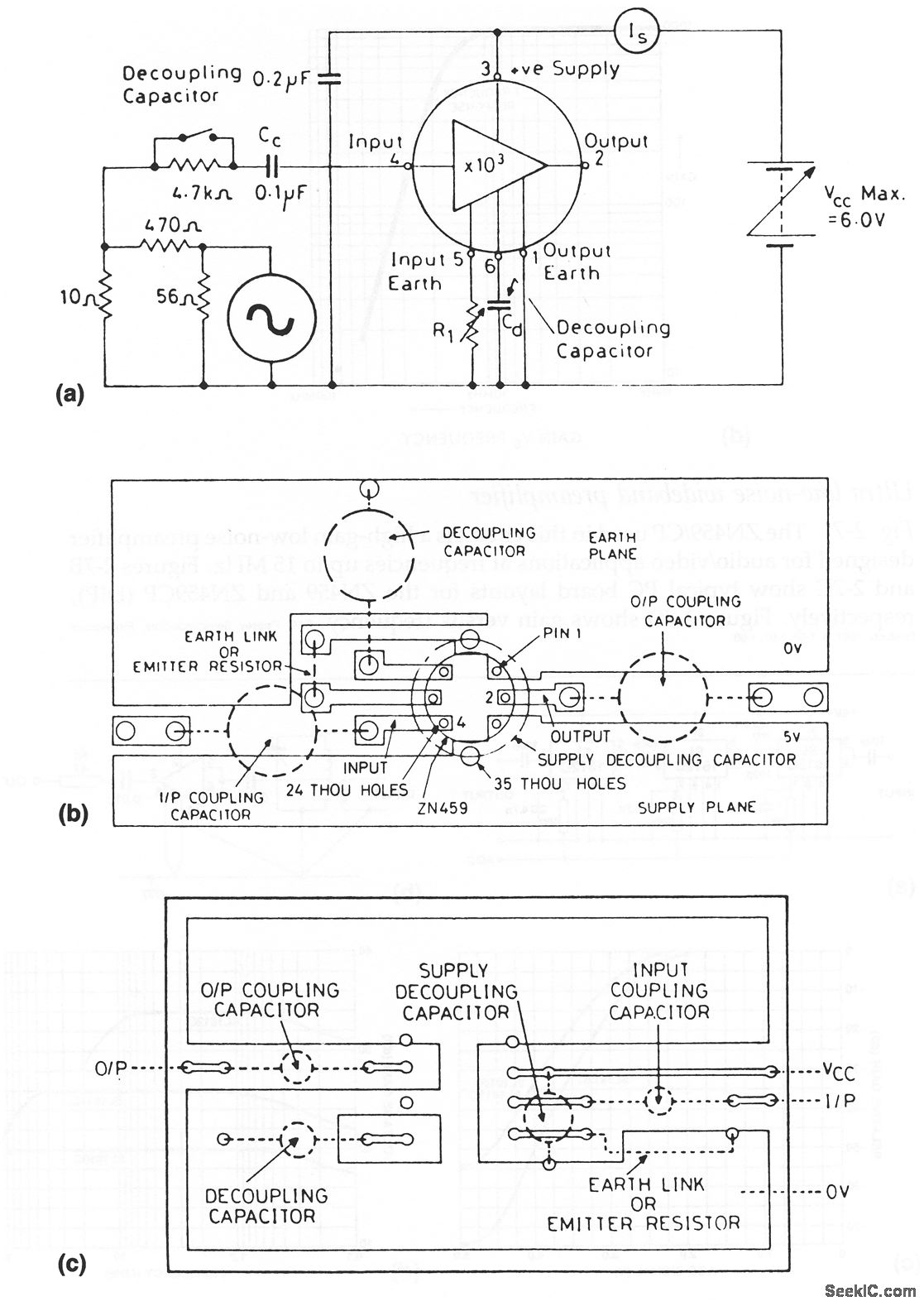
Ultra low noise wideband preamplifier
The ZN459/CP utilized in this circuit is a high-gain, low-noise preamplifier intended for audio and video applications at frequencies reaching up to 15 MHz. Figures 2-7B and 2-7C illustrate typical printed circuit board layouts for the ZN459 and ZN459CP (DIP),...
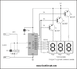
3 digits Digital volt meter
This is a simple 3-digit digital voltmeter. The PIC16F676 microcontroller is utilized to read an analog signal (voltage) and display the value on a 3-digit 7-segment display. It can also measure DC current using a parallel Rshunt, although that aspect...
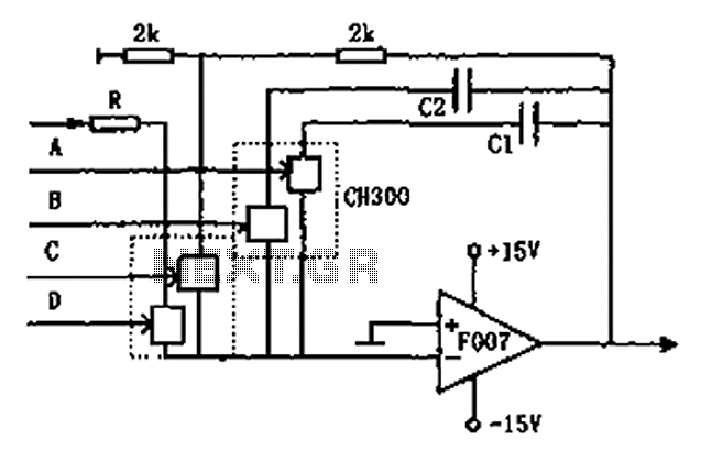
Controllable integrator F007 schematic
The circuit depicted in the figure is a controllable integrating circuit. It features a reset-to-zero function and allows for the adjustment of different integration time constants via a controllable integrator. The analog switch used is C. More specifically, it utilizes...
9400 Selling Leads 9400 Datasheet PDF
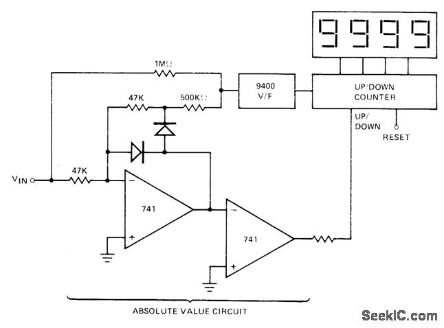
The absolute-value integrator circuit generates the effect of producing negative frequencies when the input signal is negative. It accomplishes this by allowing the counter to count up for positive voltage and count down for negative voltage. The specific types of...
Integrator-ramp-generator-with-initial-condition-reset
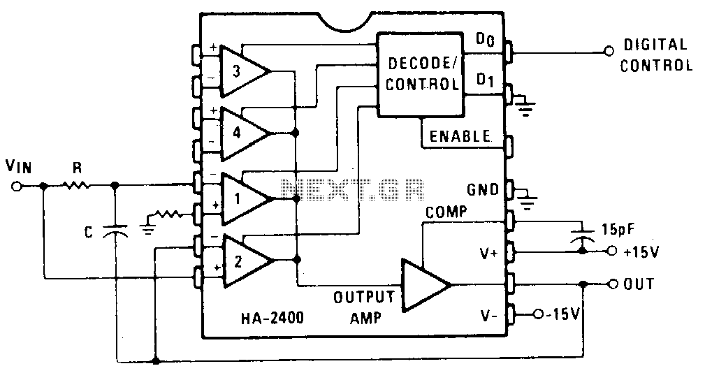
Channel 1 is configured as a conventional integrator, while Channel 2 is set up as a voltage follower. When Channel 2 is activated, the output will track the voltage of VJN, and capacitor C will discharge to maintain 0 V...
low noise oscillator design
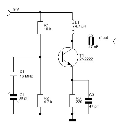
The overall performance of any RF circuit regarding its phase noise and spectral purity depends significantly on the frequency-generating circuitry, commonly an oscillator. Low noise oscillators with high spectral purity are neither mysterious nor magical. Many individuals perceive the design...
Low Noise Power Supply for Audio Circuits
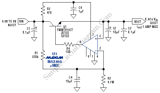
This low noise audio power supply circuit can reduce noise and ripple voltage by 40 dB over the 100 Hz to 20 kHz audio range. In portable applications such as...
This low noise audio power supply circuit is designed to significantly...
Low Noise Design Schematics
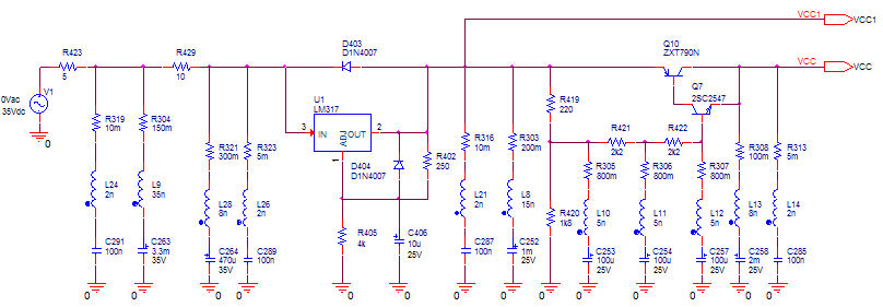
The concept of distributed active RIAA correction and the use of negative feedback to linearize the input stage is appealing. However, the original design by Collin has significant flaws, including poor power supply rejection ratio (PSRR) in the input stage....
Single-chip digital voltmeter
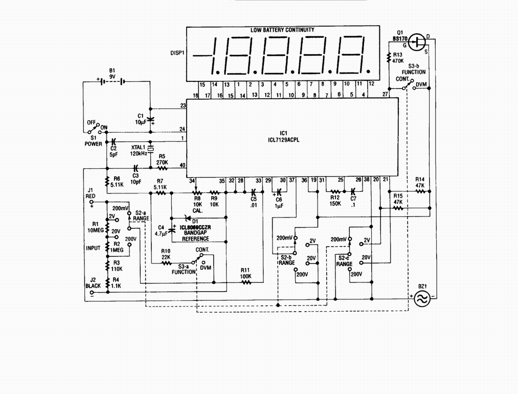
Single-chip digital voltmeter. This 4 1/2-digit DVM circuit is built around a Maxim ICL7129ACPL A/D converter and LCD driver. An ICL8069 CCZR 1.2-V band-gap reference diode is used for accuracy.
The described circuit is a single-chip digital voltmeter (DVM) utilizing the...