


Scope Probe Adapter
#scope probe
#capacitive voltage divider
#low frequency roll off
#input capacitance
#X100 voltage probe
#2 pf load
#waveform reproduction
#measurement
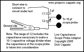
Description: The capacitance between the wire and the probe would form a capacitive voltage divider with the probe's input capacitance, and at frequencies significantly higher than the low frequency roll off created by the probe's input capacitance and the probe's resistance, the waveform would be faithfully reproduced, although it would have a reduced amplitude. The circuit given here presents about a 2 pF load to the circuit and capacitively loads the circuit measurably less than the X100 voltage probe (A Stack CP-241) often used for this sort of thing.
More: To make a X10 capacitive attenuator, simply select a variable capacitor, C2 that has an adjustment range that includes the capacitance, that when added to Cin, the input capacitance of the scope probe you are going to use with it, is nine times that of the coupling capacitor. In this circuit, the coupling capacitor, C1, is 2 pF and the scope probe's input capacitance is about 16 pF, so C2 is
C2 = (9X C1) - Cin
C2 = (9 X 2 pF) - 16 pF
C2 = 2 pF
This set of values puts 90% of the voltage across C1 and 10% across C2 and the scope probe. This also works for higher attenuations, but since signals of a few volts or less are typically used, X10 is about as high as needed.
Construction and Calibration
This circuit is constructed on a small piece of pre-punched fiberglass board with a plated metalization pattern. The leads are kept short to minimize stray reactances. A couple of centimeters of bare #30 tinned copper wire serves as the probe. A small hook at the end allows the probe to "hang" on component leads. Occasionally, the tip of the wire is soldered to the circuit under test.
A short length of hookup wire connects the adapter to an alligator clip, which provides the ground contact for the circuit under test. It is advisable to keep this wire as short as possible. For frequencies above 50 MHz, soldering a short piece of wire, approximately 1 cm long, directly from the adapter's ground to the circuit under test is recommended.
Two pieces of nickel-plated paper clip are soldered to the board to serve as connection points for the scope probe and the probe's ground clip. While a connector that accepts the probe body without the probe tip would be ideal, nickel-plated paper clips are used as a substitute in this case. Solder flux, in addition to that in the flux core solder, is applied to the paper clip during soldering to enhance the connection quality.
This design effectively creates a X10 capacitive attenuator, ensuring minimal loading on the circuit under test while maintaining signal integrity at elevated frequencies.The capacitance between the wire and the probe would form a capacitive voltage divider with the probe's input capacitance, and at frequencies significantly higher than the low frequency roll off created by the probe's input capacitance and the probe's resistance, the wave form would be faithfully reproduced, although it would have a reduced amplitude. The circuit give here, presents about a 2 pf load to the circuit, and capacitively loads the circuit measurably less than the X100 voltage probe (A Stack CP-241) I often use for this sort of thing.
To make a X10 capacitive attenuator, simply select a variable capacitor, C2 that has an adjustment range that includes the capacitance, that when added to Cin, the input capacitance of the scope probe you are going to use with it, is nine times that of the coupling capacitor. In this circuit, the coupling capacitor, C1. is 2 pf and the scope probe's input capacitance is about 16 pf, so C2 is C2 = (9X C1) - Cin C2 =( 9 X 2 pf ) -16 pf C= 2pf This set of values puts 90% of the voltage across C1 and 10% across C2 and the scope probe.
This also works for higher attenuations, but since I am working with signals of a few volts or less, X10 is about as high as I need to go. Construction and Calibration I built this on a small piece of pre-punched fiberglass board with a plated metalization pattern.
The leads are all short to minimize stray reactances. A couple cm of bare #30 tinned copper wire serves as the probe. A small hook at the end lets me "hang" the probe on component leads. I also occasionally solder the tip of the wire to the circuit under test. A short length of hookup wire makes the ground connection from the adapter to an alligator clip which makes the ground contact for the circuit under test. The shorter the better. For frequencies above 50 MHz, it would be much better to just solder a short piece of wire, about 1 cm long, from the adapter's ground to the circuit under test.
Two pieces of nickel plated paper clip are soldered to the board to serve as connection points for the scope probe and the probe's ground clip. A connector that accepts the probe body without the probe tip would be much better, and as I recall, Tektronix used to sell such connectors.
In my case, I don't have anything suitable, so I used the nickel plated paper clip. Solder flux, in addition to that in the flux core solder, was applied to the paper clip while soldering. I think it helped a lot.
More: To make a X10 capacitive attenuator, simply select a variable capacitor, C2 that has an adjustment range that includes the capacitance, that when added to Cin, the input capacitance of the scope probe you are going to use with it, is nine times that of the coupling capacitor. In this circuit, the coupling capacitor, C1, is 2 pF and the scope probe's input capacitance is about 16 pF, so C2 is
C2 = (9X C1) - Cin
C2 = (9 X 2 pF) - 16 pF
C2 = 2 pF
This set of values puts 90% of the voltage across C1 and 10% across C2 and the scope probe. This also works for higher attenuations, but since signals of a few volts or less are typically used, X10 is about as high as needed.
Construction and Calibration
This circuit is constructed on a small piece of pre-punched fiberglass board with a plated metalization pattern. The leads are kept short to minimize stray reactances. A couple of centimeters of bare #30 tinned copper wire serves as the probe. A small hook at the end allows the probe to "hang" on component leads. Occasionally, the tip of the wire is soldered to the circuit under test.
A short length of hookup wire connects the adapter to an alligator clip, which provides the ground contact for the circuit under test. It is advisable to keep this wire as short as possible. For frequencies above 50 MHz, soldering a short piece of wire, approximately 1 cm long, directly from the adapter's ground to the circuit under test is recommended.
Two pieces of nickel-plated paper clip are soldered to the board to serve as connection points for the scope probe and the probe's ground clip. While a connector that accepts the probe body without the probe tip would be ideal, nickel-plated paper clips are used as a substitute in this case. Solder flux, in addition to that in the flux core solder, is applied to the paper clip during soldering to enhance the connection quality.
This design effectively creates a X10 capacitive attenuator, ensuring minimal loading on the circuit under test while maintaining signal integrity at elevated frequencies.The capacitance between the wire and the probe would form a capacitive voltage divider with the probe's input capacitance, and at frequencies significantly higher than the low frequency roll off created by the probe's input capacitance and the probe's resistance, the wave form would be faithfully reproduced, although it would have a reduced amplitude. The circuit give here, presents about a 2 pf load to the circuit, and capacitively loads the circuit measurably less than the X100 voltage probe (A Stack CP-241) I often use for this sort of thing.
To make a X10 capacitive attenuator, simply select a variable capacitor, C2 that has an adjustment range that includes the capacitance, that when added to Cin, the input capacitance of the scope probe you are going to use with it, is nine times that of the coupling capacitor. In this circuit, the coupling capacitor, C1. is 2 pf and the scope probe's input capacitance is about 16 pf, so C2 is C2 = (9X C1) - Cin C2 =( 9 X 2 pf ) -16 pf C= 2pf This set of values puts 90% of the voltage across C1 and 10% across C2 and the scope probe.
This also works for higher attenuations, but since I am working with signals of a few volts or less, X10 is about as high as I need to go. Construction and Calibration I built this on a small piece of pre-punched fiberglass board with a plated metalization pattern.
The leads are all short to minimize stray reactances. A couple cm of bare #30 tinned copper wire serves as the probe. A small hook at the end lets me "hang" the probe on component leads. I also occasionally solder the tip of the wire to the circuit under test. A short length of hookup wire makes the ground connection from the adapter to an alligator clip which makes the ground contact for the circuit under test. The shorter the better. For frequencies above 50 MHz, it would be much better to just solder a short piece of wire, about 1 cm long, from the adapter's ground to the circuit under test.
Two pieces of nickel plated paper clip are soldered to the board to serve as connection points for the scope probe and the probe's ground clip. A connector that accepts the probe body without the probe tip would be much better, and as I recall, Tektronix used to sell such connectors.
In my case, I don't have anything suitable, so I used the nickel plated paper clip. Solder flux, in addition to that in the flux core solder, was applied to the paper clip while soldering. I think it helped a lot.
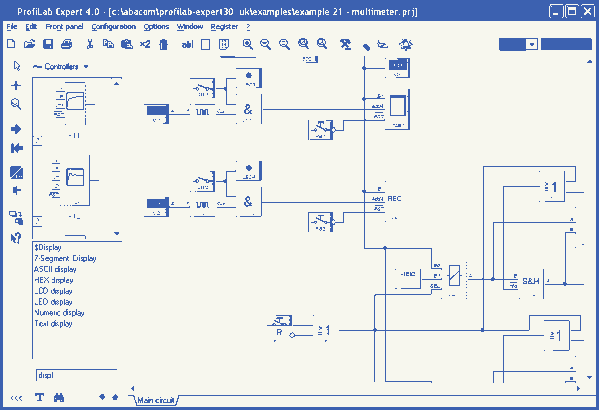
ProfiLab-Expert 4.0
The ProfiLab-Expert software allows you to develop your own digital or analogue measuring technology projects. It doesn't matter if you want to create analogue measurements or digital controls - you can realize it all. And for all this you don't...
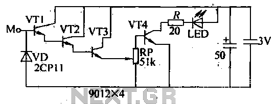
Blanket internal measurement circuit disconnection
The internal disconnection circuit for a blanket operates on the principle of induction. It includes a wire approximately 2 cm in length that senses the proximity of a charged mains power source. When the sensing wire is close to the...
ProfiLab-Expert 4.0
The ProfiLab-Expert software allows you to develop your own digital or analogue measuring technology projects. It doesn't matter if you want to create analogue measurements or digital controls - you can realize it all. And for all this you don't...
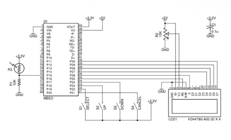
Advances in Measurement & Sensor Tech
This issue features articles on various measurement and sensor-related embedded design projects. Readers are encouraged to attempt similar projects and share their results. Starting on page 14, Petre Tzvetanov Petrov describes a multilevel audible logical probe design. Petrov notes that...
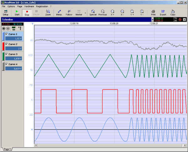
RealView 2.0
RealView is a measurement application, which records and plots measured values from analogue hardware devices in real-time. Several curves can be plotted into a single diagram. Several diagrams can be arranged on one or more pages if necessary. Plot options...
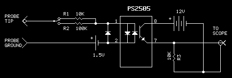
Scope Probe
Working on live telephone circuits can be a problem. You just can't connect a normal scope probe to the circuit while it is tied to the phone line. Neither side of a phone line is ground. When a phone or...
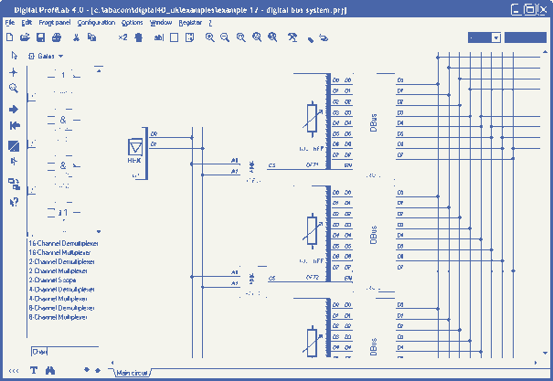
Digital-ProfiLab 4.0
Digital-ProfiLab was designed for measurement and control applications, combining features like circuit and logic simulation, front panel design, and hardware control to one powerful tool. Incoming signals from external devices may be processed and displayed. A circuit editor is used...
RealView 2.0
RealView is a measurement application, which records and plots measured values from analogue hardware devices in real-time. Several curves can be plotted into a single diagram. Several diagrams can be arranged on one or more pages if necessary. Plot options...
Digital-ProfiLab 4.0
Digital-ProfiLab was designed for measurement and control applications, combining features like circuit and logic simulation, front panel design, and hardware control to one powerful tool. Incoming signals from external devices may be processed and displayed. A circuit editor is used...