


Scope Probe
#scope probe
#optocoupler
#telephone circuits
#floating circuits
#voltage measurement
#isolation
#diode protection
#live circuit
#negative voltage
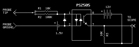
Description: Working on live telephone circuits can be a problem. You just can't connect a normal scope probe to the circuit while it is tied to the phone line. Neither side of a phone line is ground. When a phone or other device is 'off-hook', one side floats at about -22 volts and the other side about -30 volts. This probe allows connecting to such 'floating' circuits to a normal scope input. As seen in the circuit, it is based on using an optocoupler. The one shown in the diagram is a dual unit, but I had a pile of them here, so that's what I used. Because this device responds to both polarities, an external diode was added to prevent negative voltages from producing an output. The input has 2 ranges: 1 to 1, and 10 to 1. There is no need for a power switch because with no input, virtually no power is drawn from the 12 volt (keyfob) battery. Also, no power is drawn from the 1.5 volt (watch) battery.
Because of variations in individual optocouplers, you should select a value for R3 to get the best results.
Now for the bad news.....
This device is inherently non-linear. The small battery on the input side helps compensate by giving an initial bias to the optocoupler's input LED. Also, presenting a 10k load to some circuits will cause additional error in the output. The non-linearity is not too bad from 0 to 5 volts; above that, it is not very usable.
Nonetheless, this little gadget has already 'paid for itself' in making some timing and voltage measurements of how a circuit responds to a telephone ring signal.
This circuit is designed to safely interface with live telephone lines for measurement purposes. The primary component of the circuit is an optocoupler, which provides electrical isolation between the high-voltage telephone line and the measuring equipment, such as an oscilloscope. The optocoupler's LED is biased using a small battery, allowing it to function correctly even when the telephone line is floating at negative voltages.
The circuit features two input ranges: a direct 1:1 ratio and a 10:1 ratio, enabling flexibility in measuring different voltage levels. The absence of a power switch is a deliberate design choice, as the circuit draws negligible power when not in use, thanks to the low consumption characteristics of the optocoupler and the biasing battery.
It is important to note that the performance of the circuit may vary based on the specific optocoupler used, necessitating the adjustment of resistor R3 to optimize the output response. The design acknowledges the inherent non-linearity of the system, particularly at higher voltage levels. While the output is reliable and accurate within the 0 to 5 volts range, deviations may occur beyond this threshold, especially when interfaced with loads such as a 10k resistor.
In application, this device proves beneficial for measuring the response characteristics of telephone circuits, such as detecting ringing signals and assessing timing measurements, thereby providing valuable insights without the risk of damaging sensitive measuring equipment.Working on live telephone circuits can be a problem. You just can't connect a normal scope probe to the circuit while it is tied to the phone line. Neather side of a phone line is ground. When a phone or other device is 'offhook', one side floats at about -22 volts and the other side about -30 volts. This probe allows connecting to such 'floating' circuits to a normal scope input. As seen in the circuit, it is based on using an optocoupler. The one shown in the diagram is a dual unit, but I had a pile of them here, so thats what I used. Because this device responds to both polarities, an external diode was added to prevent negative voltages from producting an output.
The input has 2 ranges: 1 to 1, and 10 to 1. There is no need for a power switch because with no input, virtually no power is drawn from the 12 volt (keyfob) battery. Also, no power is drawn from the 1.5 volt (watch) battery. Because of variations in individual optocouplers, you should select a value for R3 to get the best results.
Now for the bad news..... This device is enherently non-linear. The small battery on the input side helps compensate by giving an initial bias to the optocoupler's input LED. Also, presenting a 10k load to some circuits will cause addional error in the output. The non-linearity is not too bad from 0 to 5 volts, above that, it is not very usable. Nonetheless, this little gadget has already 'paid for itself' in making some timing and voltage measurments of how a circuit responds to a telephone ring signal.
Because of variations in individual optocouplers, you should select a value for R3 to get the best results.
Now for the bad news.....
This device is inherently non-linear. The small battery on the input side helps compensate by giving an initial bias to the optocoupler's input LED. Also, presenting a 10k load to some circuits will cause additional error in the output. The non-linearity is not too bad from 0 to 5 volts; above that, it is not very usable.
Nonetheless, this little gadget has already 'paid for itself' in making some timing and voltage measurements of how a circuit responds to a telephone ring signal.
This circuit is designed to safely interface with live telephone lines for measurement purposes. The primary component of the circuit is an optocoupler, which provides electrical isolation between the high-voltage telephone line and the measuring equipment, such as an oscilloscope. The optocoupler's LED is biased using a small battery, allowing it to function correctly even when the telephone line is floating at negative voltages.
The circuit features two input ranges: a direct 1:1 ratio and a 10:1 ratio, enabling flexibility in measuring different voltage levels. The absence of a power switch is a deliberate design choice, as the circuit draws negligible power when not in use, thanks to the low consumption characteristics of the optocoupler and the biasing battery.
It is important to note that the performance of the circuit may vary based on the specific optocoupler used, necessitating the adjustment of resistor R3 to optimize the output response. The design acknowledges the inherent non-linearity of the system, particularly at higher voltage levels. While the output is reliable and accurate within the 0 to 5 volts range, deviations may occur beyond this threshold, especially when interfaced with loads such as a 10k resistor.
In application, this device proves beneficial for measuring the response characteristics of telephone circuits, such as detecting ringing signals and assessing timing measurements, thereby providing valuable insights without the risk of damaging sensitive measuring equipment.Working on live telephone circuits can be a problem. You just can't connect a normal scope probe to the circuit while it is tied to the phone line. Neather side of a phone line is ground. When a phone or other device is 'offhook', one side floats at about -22 volts and the other side about -30 volts. This probe allows connecting to such 'floating' circuits to a normal scope input. As seen in the circuit, it is based on using an optocoupler. The one shown in the diagram is a dual unit, but I had a pile of them here, so thats what I used. Because this device responds to both polarities, an external diode was added to prevent negative voltages from producting an output.
The input has 2 ranges: 1 to 1, and 10 to 1. There is no need for a power switch because with no input, virtually no power is drawn from the 12 volt (keyfob) battery. Also, no power is drawn from the 1.5 volt (watch) battery. Because of variations in individual optocouplers, you should select a value for R3 to get the best results.
Now for the bad news..... This device is enherently non-linear. The small battery on the input side helps compensate by giving an initial bias to the optocoupler's input LED. Also, presenting a 10k load to some circuits will cause addional error in the output. The non-linearity is not too bad from 0 to 5 volts, above that, it is not very usable. Nonetheless, this little gadget has already 'paid for itself' in making some timing and voltage measurments of how a circuit responds to a telephone ring signal.
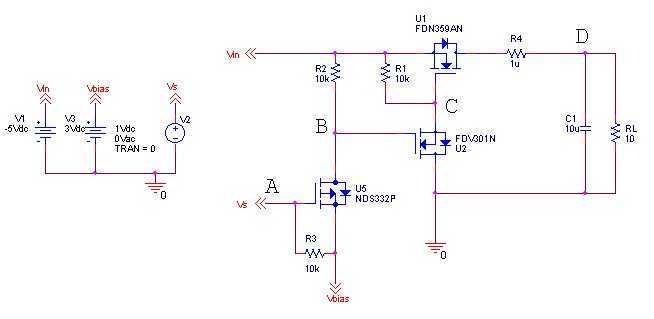
Negative Voltage Load Swtich
The idea is simply to turn off the negative voltage load. Some examples: - Bias voltages for LCD panels - RF Amplifiers - Audio Amplifiers
The good thing about this design is that I can make use of the system I/O...
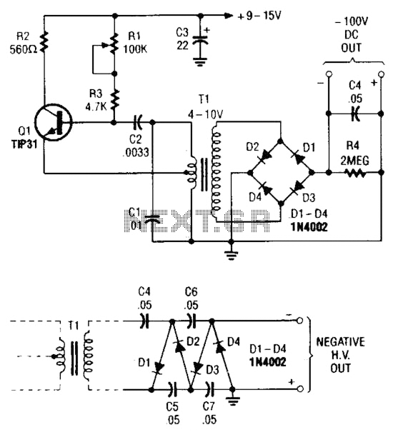
Negative Voltage Supply Circuit
The combination of a Hartley oscillator and a step-up transformer can generate significant negative high voltage, particularly when the voltage output of the transformer is multiplied by the circuit.
The Hartley oscillator is a type of LC oscillator that utilizes an...
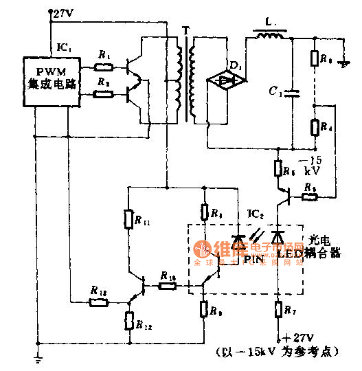
High voltage speed optocoupler and application circuit diagram
The technical parameters of high-speed optocouplers include a rise time (t1) of less than or equal to 300 ns, a circuit transfer ratio (CTR) of 50%, an isolation voltage (VSO) of at least 15,000 V, and an output transistor reverse...
Secondary-Side Optocoupler Driver
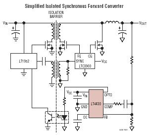
The LT4430 drives the opto-coupler that crosses the galvanic barrier in an isolated power supply. The IC contains a precision-trimmed reference, a high bandwidth error amplifier, an inverting gain of 6 stage to drive the opto-coupler, and unique overshoot control...
Stable optocoupler
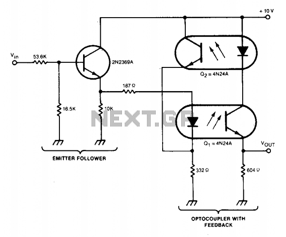
A circuit stabilizes the current-transfer ratio (CTR) of an optically coupled isolator used as a linear transducer. The optocoupler produces a voltage output that is proportional to, but electrically isolated from, the voltage input. However, the output voltage is directly...
EIGHT CHANNEL COMPUTERIZED 3SUP1 SUP SUB2 SUB DIGIT_VM
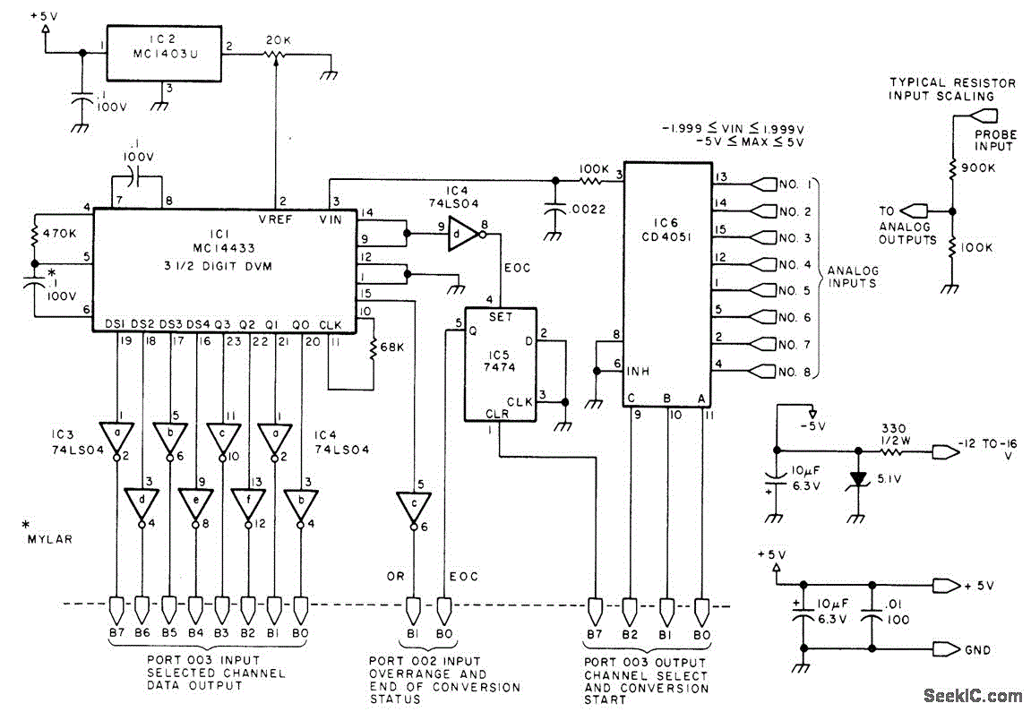
Displays up to eight different DC voltages on a CRT terminal of a microprocessor under keyboard control, using BASIC commands and a BASIC routine provided in the article. Utilizes a modified Motorola MC14433 dual-lamp integrating analog-to-digital converter. An unknown voltage...
The Measurements for MIT 3DL1 Run
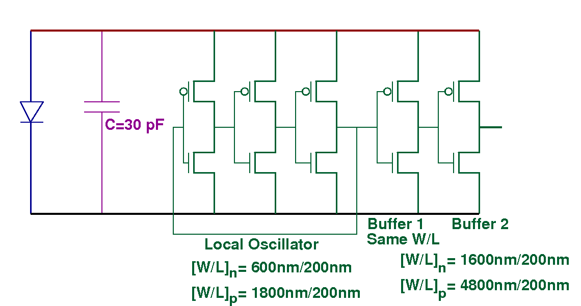
The chips that are classified as "working well" produce approximately 300 mV when exposed to a laser pointer and between 40 to 80 mV when illuminated by LED light. Voltages around 100 mV were recorded in a sunlit environment, while...
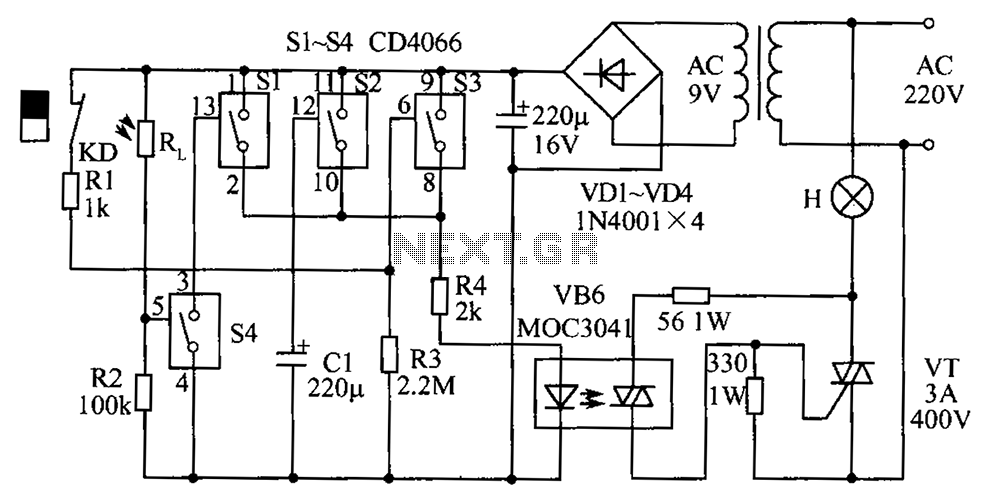
Automatic lighting control circuit diagram composed of optocouplers
The circuit diagram illustrates a group of four analog electronic circuit switches (S1 to S4). Switches S1, S2, and S3 are utilized in a parallel delay circuit. When the power is activated, resistor R4 drives the triac VT, which directly...
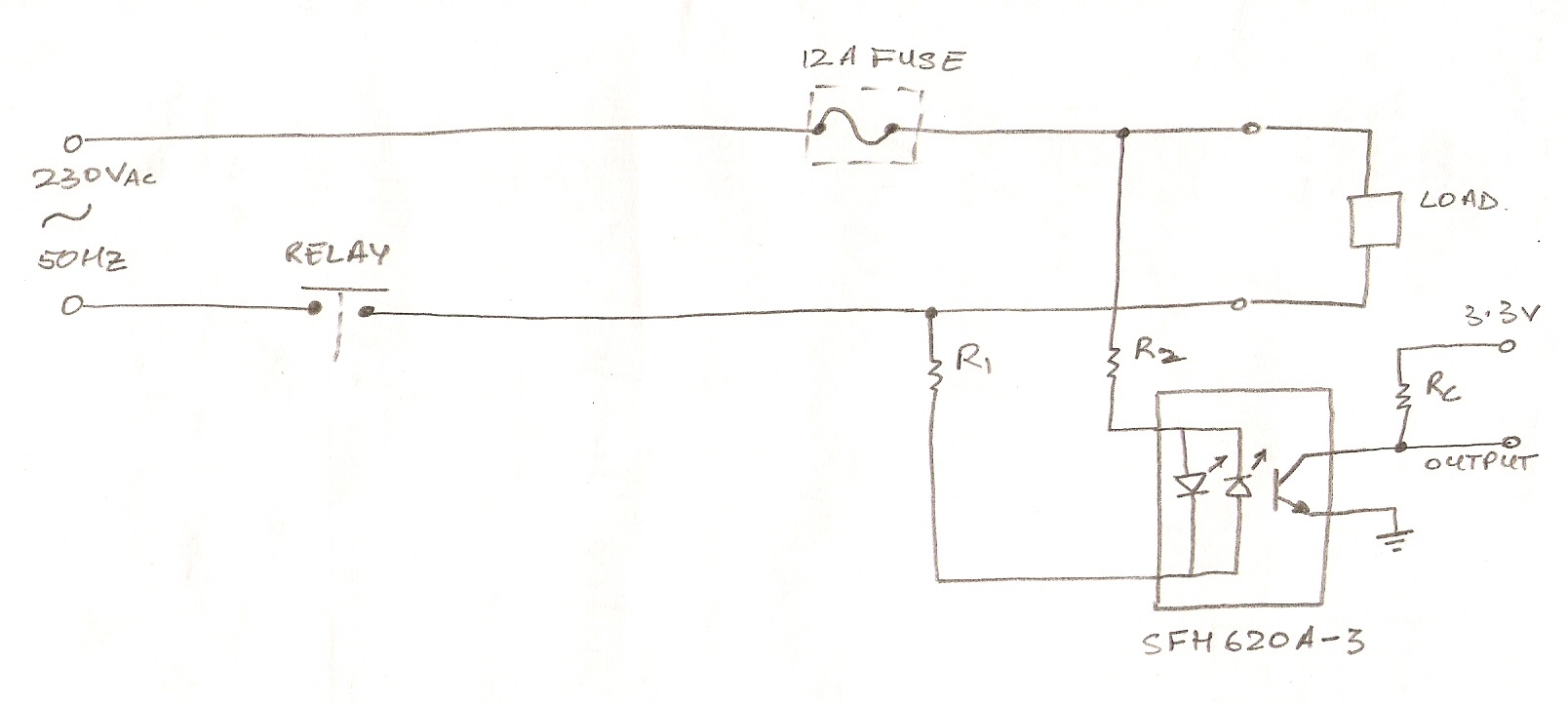
power supply How do I select the accompanying components for an optocoupler
The circuit utilizes an optocoupler (MOC3021) to detect the On/Off state of an electrical appliance using a microcontroller (ATmega16L). The mains supply specifications are 230V, 50Hz. The design aims to determine whether the load is active or inactive. The output...