


Solid-Motion
#Dataq DI-194RS
#Dataq DI-154RS
#PCB
#data acquisition
#sensors
#modifications
#measurement
#instrumentation
#hardware
#electronics
Description: Several easy modifications can be made to the Dataq DI-194RS and DI-154RS models. These devices come in two styles: packaged (as shown) and unpackaged PCB versions. The unpackaged versions are typically received when obtaining Dataq's free PCB offer. This guide specifically addresses modifications for the packaged 194RS and 154RS models. The unpackaged version features a distinct power section and is labeled "DI194 Rev G" on the PCB, while the packaged model is marked "DI194/154 Rev G." The modifications described are independent of one another, allowing for selective implementation. No specialized tools are required for these modifications. The modifications include the conversion of channels to unipolar input, which is beneficial for sensors based on bridge circuits, such as load cells, strain gauges, and pressure sensors, as it enhances converter resolution. Calibration instructions for using a load cell with the Dataq devices are available. A schematic illustrating the modifications can be downloaded and viewed with ExpressPCB schematics. Dataq also provides a comprehensive schematic of the DI-194RS circuit, excluding the RS232 transmit/receive level-translation/buffer circuit. Notably, R24 (a black surface mount resistor) is located beneath the gray potentiometer, which will be removed during the modifications. R1 (a light blue surface mount resistor) is positioned upside down at the lower right.
To convert a channel from ±10V bipolar input to a 0-10V unipolar input, one resistor per channel must be removed. In the provided picture, R1 is removed to change channel 1 to a 0-10V unipolar input. Removing a surface mount resistor can be accomplished with a standard low-wattage soldering iron, though it requires some practice. The recommended technique involves heating one side of the resistor for one to two seconds, then switching to the opposite side for a similar duration. Returning to the first side for half a second and flicking the soldering iron tip sideways will typically release the resistor. The overall sequence is: first-side, second-side, first-side, flick. An alternative bipolar/unipolar option is available; the jumper JP2 is set by default to the "Bipolar" position for ±10V input. Moving the jumper to the nearest position to the connector enables "Unipolar" 0-20V input for all channels. However, once resistors are removed, the jumper setting only affects the channels for which the resistors have been removed.
The next step involves modifying the external supply. R24 should be removed as previously indicated. If only external power will be utilized, Step 4 can be bypassed. Dataq outlines another method for adding external power that requires surface mount components and is specific to a particular battery voltage. The method described here is simpler and more adaptable, albeit requiring an additional connector. Step 4 introduces a diode for automatic switching between internal and external power supplies. A 1N914 diode should be installed in series with a 100-ohm resistor across the pads previously occupied by R24. The cathode (striped side) of the diode must be connected to the resistor. A 1/8 watt resistor is ideal due to its compact size, but a 1/4 watt resistor can also be used with careful lead bending. The leads should be trimmed and bent at a right angle to fit the pads as illustrated. This diode and resistor configuration will permit the use of either serial port power or external power. When external power is applied, the diode prevents the external supply from feeding back into the serial port.
Before proceeding with the addition of external power wiring, it is essential to ensure that all modifications are correctly implemented and that the circuit is properly configured to avoid any potential issues.Several easy modifications for a Dataq DI-194RS and DI-154RS. There are at least two different styles: the kind that come packaged (shown) and the kind that come as an unpackaged PCB. The unpackaged ones are what you get when you are fortunate enough to get Dataq's free PCB. These instructions cover the packaged 194RS and 154RS only. T he unpackaged version has a completely different power section and is marked "DI194 Rev G" on the PCB, while the packaged model is marked "DI194/154 Rev G". The mods shown here are independent of each other so make as few or as many as you like. No special tools are needed for any of these mods. The modifications outlined below include: Why convert channels to unipolar Because any sensor that you are using that is based on a bridge circuit only needs a unipolar input and you'll double your converter resolution by going to unipolar.
Loadcells, strain gages and pressure sensors are all examples of bridge based sensors that will benefit from unipolar conversion. There are instructions on calibrating the Dataq when used with a loadcell at Calibrating an SGA01 with a Dataq DI-154RS or DI-194RS.
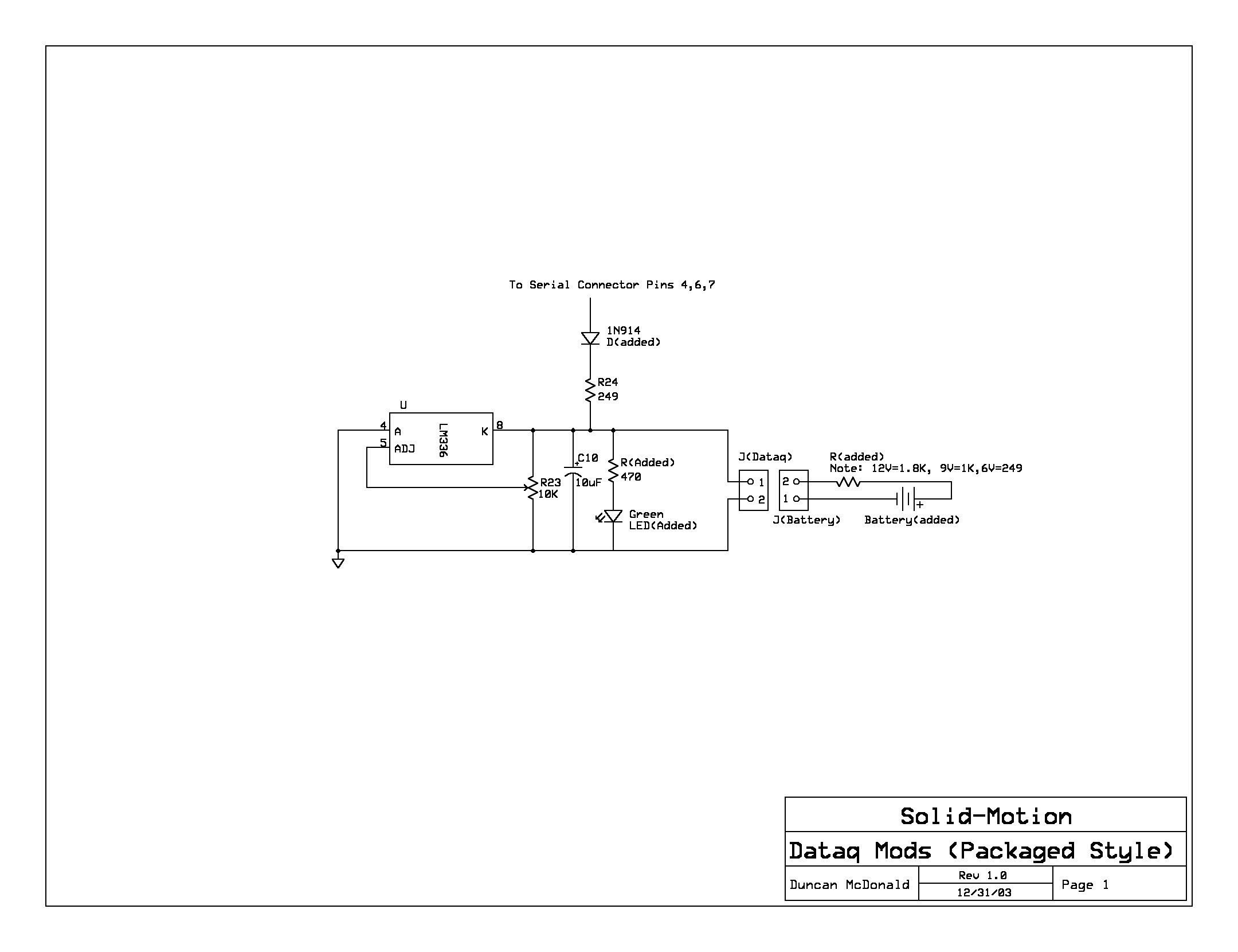
Below is a schematic outlining the modifications. You can also download it and view it with ExpressPCB schematics. Dataq also has a decent schematic you can view that shows the entire DI-194RS circuit minus the RS232 transmit/receive level-translation/buffer circuit. Notice R24 (black surface mount resistor) right below the grey potentiometer. We'll remove R24 in a moment. R1 (light blue surface mount resistor) is upside down at the lower right. Step 2. To convert a channel from ±10V bipolar input to 0-10V unipolar input, one resistor per channel has to be removed.
In the picture above, R1 is removed to make channel 1 0-10V unipolar input. It is quite easy to remove a surface mount resistor with a normal low wattage soldering iron, but it takes a little practice. First place the soldering iron tip on one side of the resistor for one or two seconds. Then quickly move the soldering iron to the other side for one or two seconds. Now move the soldering iron tip back to the first side for about half a second and then give the tip a quick flick to the side.
The resistor should come right off. The overall sequence is: first-side, second-side, first-side, flick. There is one other bipolar/unipolar option. Jumper JP2 is set by default to the "Bipolar" setting for ±10V bipolar input. Moving the jumper to the position closest to the connector will give you "Unipolar" 0-20V input for all channels. Once resistors are removed though, it doesn't matter what the jumper setting is only for the channel(s) for which you have removed the resistor(s).
Step 3. Now, on to the external supply. First remove R24 as shown above. If you will only be using an external supply you can skip Step 4. Dataq documents another approach to adding external power, put it involves adding surface mount components and the mod must be made for a specific battery voltage. The approach documented here is easier to perform and is more flexible, but it does require an additional connector.
Step 4. This step adds a diode so that you will have automatic switching between an internal and external supply. Add a 1N914 diode in series with a 100 ohm resistor across the pads that R24 used to sit on. The stripe side of the diode (cathode) should be connected to the resistor. A 1/8 watt resistor is a good size to use here because it is so small, but a 1/4 watt will also work if you bend the leads carefully.
Trim the leads and bend them at a right angle so that they sit on the pads as shown below. This diode and resistor will allow either the serial port power to be used or external power. When external power is applied the diode will block the external supply from trying to put power back onto the serial port. Step 5. Before adding the external power wiring, let'
To convert a channel from ±10V bipolar input to a 0-10V unipolar input, one resistor per channel must be removed. In the provided picture, R1 is removed to change channel 1 to a 0-10V unipolar input. Removing a surface mount resistor can be accomplished with a standard low-wattage soldering iron, though it requires some practice. The recommended technique involves heating one side of the resistor for one to two seconds, then switching to the opposite side for a similar duration. Returning to the first side for half a second and flicking the soldering iron tip sideways will typically release the resistor. The overall sequence is: first-side, second-side, first-side, flick. An alternative bipolar/unipolar option is available; the jumper JP2 is set by default to the "Bipolar" position for ±10V input. Moving the jumper to the nearest position to the connector enables "Unipolar" 0-20V input for all channels. However, once resistors are removed, the jumper setting only affects the channels for which the resistors have been removed.
The next step involves modifying the external supply. R24 should be removed as previously indicated. If only external power will be utilized, Step 4 can be bypassed. Dataq outlines another method for adding external power that requires surface mount components and is specific to a particular battery voltage. The method described here is simpler and more adaptable, albeit requiring an additional connector. Step 4 introduces a diode for automatic switching between internal and external power supplies. A 1N914 diode should be installed in series with a 100-ohm resistor across the pads previously occupied by R24. The cathode (striped side) of the diode must be connected to the resistor. A 1/8 watt resistor is ideal due to its compact size, but a 1/4 watt resistor can also be used with careful lead bending. The leads should be trimmed and bent at a right angle to fit the pads as illustrated. This diode and resistor configuration will permit the use of either serial port power or external power. When external power is applied, the diode prevents the external supply from feeding back into the serial port.
Before proceeding with the addition of external power wiring, it is essential to ensure that all modifications are correctly implemented and that the circuit is properly configured to avoid any potential issues.Several easy modifications for a Dataq DI-194RS and DI-154RS. There are at least two different styles: the kind that come packaged (shown) and the kind that come as an unpackaged PCB. The unpackaged ones are what you get when you are fortunate enough to get Dataq's free PCB. These instructions cover the packaged 194RS and 154RS only. T he unpackaged version has a completely different power section and is marked "DI194 Rev G" on the PCB, while the packaged model is marked "DI194/154 Rev G". The mods shown here are independent of each other so make as few or as many as you like. No special tools are needed for any of these mods. The modifications outlined below include: Why convert channels to unipolar Because any sensor that you are using that is based on a bridge circuit only needs a unipolar input and you'll double your converter resolution by going to unipolar.
Loadcells, strain gages and pressure sensors are all examples of bridge based sensors that will benefit from unipolar conversion. There are instructions on calibrating the Dataq when used with a loadcell at Calibrating an SGA01 with a Dataq DI-154RS or DI-194RS.
Below is a schematic outlining the modifications. You can also download it and view it with ExpressPCB schematics. Dataq also has a decent schematic you can view that shows the entire DI-194RS circuit minus the RS232 transmit/receive level-translation/buffer circuit. Notice R24 (black surface mount resistor) right below the grey potentiometer. We'll remove R24 in a moment. R1 (light blue surface mount resistor) is upside down at the lower right. Step 2. To convert a channel from ±10V bipolar input to 0-10V unipolar input, one resistor per channel has to be removed.
In the picture above, R1 is removed to make channel 1 0-10V unipolar input. It is quite easy to remove a surface mount resistor with a normal low wattage soldering iron, but it takes a little practice. First place the soldering iron tip on one side of the resistor for one or two seconds. Then quickly move the soldering iron to the other side for one or two seconds. Now move the soldering iron tip back to the first side for about half a second and then give the tip a quick flick to the side.
The resistor should come right off. The overall sequence is: first-side, second-side, first-side, flick. There is one other bipolar/unipolar option. Jumper JP2 is set by default to the "Bipolar" setting for ±10V bipolar input. Moving the jumper to the position closest to the connector will give you "Unipolar" 0-20V input for all channels. Once resistors are removed though, it doesn't matter what the jumper setting is only for the channel(s) for which you have removed the resistor(s).
Step 3. Now, on to the external supply. First remove R24 as shown above. If you will only be using an external supply you can skip Step 4. Dataq documents another approach to adding external power, put it involves adding surface mount components and the mod must be made for a specific battery voltage. The approach documented here is easier to perform and is more flexible, but it does require an additional connector.
Step 4. This step adds a diode so that you will have automatic switching between an internal and external supply. Add a 1N914 diode in series with a 100 ohm resistor across the pads that R24 used to sit on. The stripe side of the diode (cathode) should be connected to the resistor. A 1/8 watt resistor is a good size to use here because it is so small, but a 1/4 watt will also work if you bend the leads carefully.
Trim the leads and bend them at a right angle so that they sit on the pads as shown below. This diode and resistor will allow either the serial port power to be used or external power. When external power is applied the diode will block the external supply from trying to put power back onto the serial port. Step 5. Before adding the external power wiring, let'
Advances in Measurement & Sensor Tech
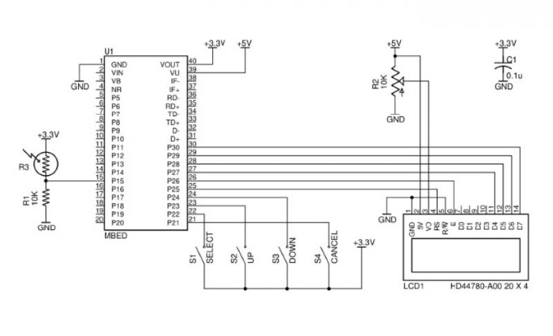
This issue features articles on various measurement and sensor-related embedded design projects. Readers are encouraged to attempt similar projects and share their results. Starting on page 14, Petre Tzvetanov Petrov describes a multilevel audible logical probe design. Petrov notes that...
RealView 2.0
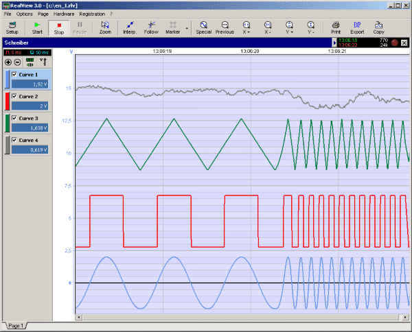
RealView is a measurement application, which records and plots measured values from analogue hardware devices in real-time. Several curves can be plotted into a single diagram. Several diagrams can be arranged on one or more pages if necessary. Plot options...
Multi-channel data acquisition ISO100 isolation circuit of a programmable gain amplifier
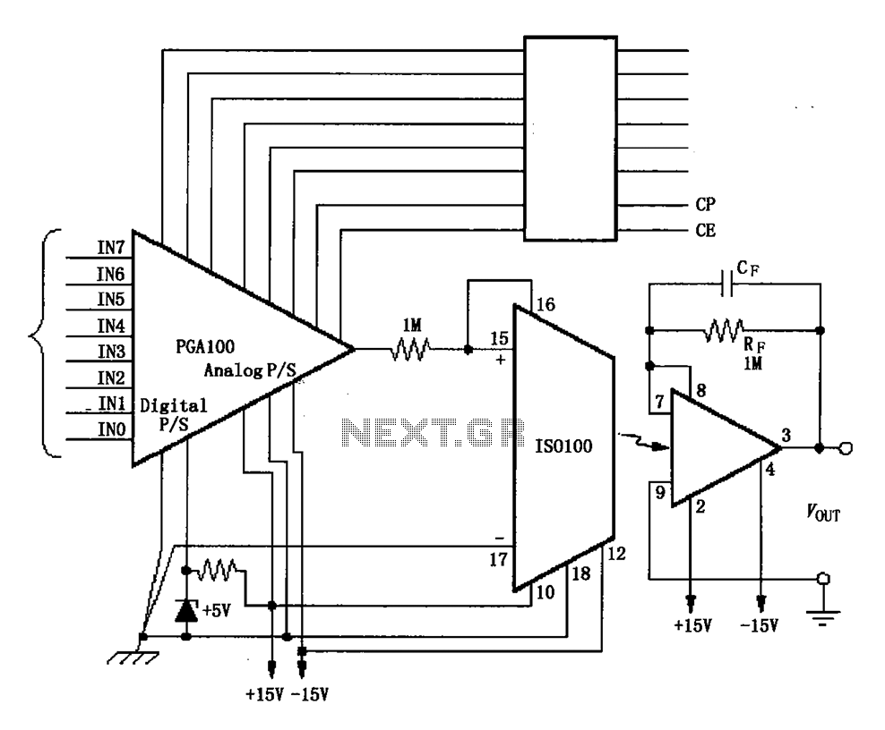
The ISO100 multichannel data acquisition system comprises a programmable gain amplifier isolated by an optocoupler, a programmable amplifier (PGA100), and an isolation amplifier (ISO100). The optocoupler selects three channels and is coupled to the programmable gain amplifier, which can select...
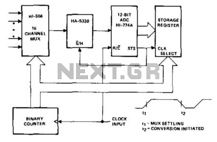
Data Acquisition System I
The HI-506 multiplexer functions as an analog input selector, which is controlled by a binary counter to select the appropriate channel. The HA-5330 serves as a high-speed sample and hold circuit. The sample/hold control is connected to the status (STS)...
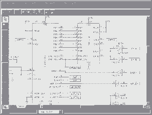
Express PCB
Our Free PCB software is a snap to learn and use. For the first time, designing circuit boards is simple for the beginner and efficient for the professional. Our board manufacturing service makes top quality two and four layer PCBs....
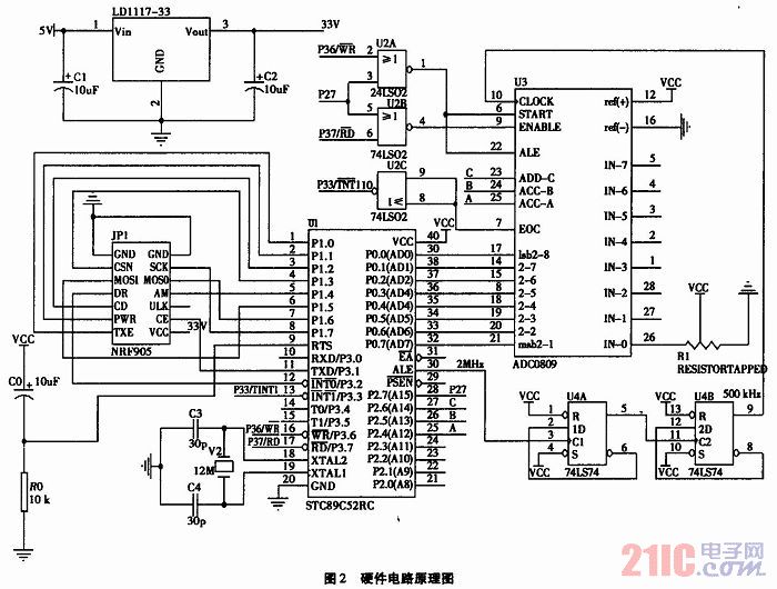
Based on one-chip computer data acquisition and wireless to receive and dispatch studying systematic
The technology of data acquisition is an important branch of information science. It is not only employed in intelligent instruments but is also widely used in modern industrial production and military science. This technology is essential for process control, condition...
Proximity Camera Head (A2047) Manual
The Proximity Camera Head (A2047) is a Long-Wire Data Acquisition (LWDAQ) device that interfaces with a TC255P image sensor. It is a radiation-tolerant evolution of the Inplane Sensor Head (A2036). The A2036 and A2033 are frequently used with the LWDAQ...
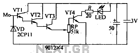
Blanket internal measurement circuit disconnection
The internal disconnection circuit for a blanket operates on the principle of induction. It includes a wire approximately 2 cm in length that senses the proximity of a charged mains power source. When the sensing wire is close to the...
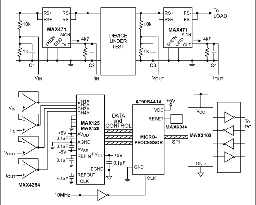
Practical Data Acquisition using a Windows based Power Meter
This application note outlines the design of a PC-based, 14-bit data acquisition system. It adopts a systematic approach, incorporating all essential components: analog, digital, hardware, and software. The document elaborates on each phase, emphasizing the testing of individual systems prior...