


Thermistor Thermometer circuit
#thermistor
#ADC
#microcontroller
#temperature measurement
#LED display
#digital filtering
#sensor interface
#educational
#C programming
#12-bit resolution
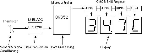
Description: This assignment pertains to the course "Designing Microprocessor Based Instrumentation." The project features a board that utilizes a 12-bit ADC, a C program with digital filtering, and an LED display interface. It achieves a temperature reading sensitivity of 0.1°C. An optional ADC input is available for experimentation with different input signals or sensors. The hardware block diagram is depicted in Fig. 2. The temperature sensor employed is an epoxy-molded thermistor. A simple voltage divider circuit is used for signal conditioning. The ADC used is the LTC1298, a 12-bit SPI interface analog-to-digital converter. The microcontroller selected is the ATMEL 89S52. The display consists of four 0.5-inch 7-segment LEDs. The segment driver provides a 32-bit CMOS output. The complete hardware schematic is illustrated in Fig. 3. The ADC, which can be either the LTC1298 or the MC3202, features two channels: CH0 and CH1. The input signal from the thermistor is connected to ADC channel 0 via a simple voltage divider, while channel 1 is available for other sensors. An example of an additional sensor in the schematic is the HIH-3160 Honeywell Relative Humidity Sensor. The ADC chip interfaces with the microcontroller (89S52) through pins P1.1, P1.2, and P1.3. The 4-digit LED display is driven directly by a 4094 CMOS shift register.
The described circuit is a microprocessor-based instrumentation system designed for temperature and humidity measurement. The heart of the system is the LTC1298 analog-to-digital converter, which provides high-resolution digital output from the analog signals received from the thermistor and an optional humidity sensor. The thermistor's output is conditioned using a voltage divider, ensuring that the voltage level fed into the ADC is within its operational range.
The microcontroller, ATMEL 89S52, orchestrates the entire operation, executing the C program that includes digital filtering algorithms to refine the raw ADC data. This filtering enhances measurement accuracy by minimizing noise and fluctuations in the readings. The microcontroller communicates with the ADC via a Serial Peripheral Interface (SPI), allowing for efficient data transfer and control.
The 4-digit 7-segment LED display provides a clear visual representation of the temperature readings, with a sensitivity of 0.1°C, making it suitable for applications requiring precise temperature monitoring. The display is driven by a 4094 CMOS shift register, which allows for efficient control of the LED segments through the microcontroller's output pins.
The design also incorporates an optional input channel for the ADC, facilitating the integration of additional sensors. In this case, the HIH-3160 Honeywell Relative Humidity Sensor can be connected to channel 1, enabling simultaneous measurement of temperature and humidity. This versatility enhances the system's applicability in various environmental monitoring scenarios.
Overall, the circuit design emphasizes simplicity and effectiveness, making it a suitable project for educational purposes in microprocessor-based instrumentation. The use of well-established components and interfaces ensures reliability and ease of implementation.This is my student assignment for the class "Designing Microprocessor Based Instrumentation". The board demonstrates the use of 12-bit ADC, writing c program with digital filtering and interface the LED display. The reading provides 0. 1C sensitivity. The optional input of the ADC is available for exercise with other input signals or sensors. The h ardware block diagram is shown in Fig. 2. The sensor is epoxy molded thermistor. The circuit for signal conditioning is simple voltage divider. The ADC is 12-bit SPI interface LTC1298 analog-to-digital converter. The microcontroller is ATMEL 89S52. The display has four digits 0. 5 inches 7-segment LED. The segment driver provides 32-bit CMOS output. The complete hardware schematic is shown in Fig 3. The ADC is 12-bit SPI interface LTC1298 or MC3202. There are two channels, CH0 and CH1. The input signal from thermistor for ADC channel 0 is simple voltage divider. Channel1 is available for other sensor. The sample shown in schematic is HIH-3160 Honeywell Relative Humidity Sensor. The ADC chip is interfaced with MCU, 89S52 with P1. 1, P1. 2 and P1. 3. The display has 4-digit LED. The 4094 CMOS shift register drives the LED directly.
The described circuit is a microprocessor-based instrumentation system designed for temperature and humidity measurement. The heart of the system is the LTC1298 analog-to-digital converter, which provides high-resolution digital output from the analog signals received from the thermistor and an optional humidity sensor. The thermistor's output is conditioned using a voltage divider, ensuring that the voltage level fed into the ADC is within its operational range.
The microcontroller, ATMEL 89S52, orchestrates the entire operation, executing the C program that includes digital filtering algorithms to refine the raw ADC data. This filtering enhances measurement accuracy by minimizing noise and fluctuations in the readings. The microcontroller communicates with the ADC via a Serial Peripheral Interface (SPI), allowing for efficient data transfer and control.
The 4-digit 7-segment LED display provides a clear visual representation of the temperature readings, with a sensitivity of 0.1°C, making it suitable for applications requiring precise temperature monitoring. The display is driven by a 4094 CMOS shift register, which allows for efficient control of the LED segments through the microcontroller's output pins.
The design also incorporates an optional input channel for the ADC, facilitating the integration of additional sensors. In this case, the HIH-3160 Honeywell Relative Humidity Sensor can be connected to channel 1, enabling simultaneous measurement of temperature and humidity. This versatility enhances the system's applicability in various environmental monitoring scenarios.
Overall, the circuit design emphasizes simplicity and effectiveness, making it a suitable project for educational purposes in microprocessor-based instrumentation. The use of well-established components and interfaces ensures reliability and ease of implementation.This is my student assignment for the class "Designing Microprocessor Based Instrumentation". The board demonstrates the use of 12-bit ADC, writing c program with digital filtering and interface the LED display. The reading provides 0. 1C sensitivity. The optional input of the ADC is available for exercise with other input signals or sensors. The h ardware block diagram is shown in Fig. 2. The sensor is epoxy molded thermistor. The circuit for signal conditioning is simple voltage divider. The ADC is 12-bit SPI interface LTC1298 analog-to-digital converter. The microcontroller is ATMEL 89S52. The display has four digits 0. 5 inches 7-segment LED. The segment driver provides 32-bit CMOS output. The complete hardware schematic is shown in Fig 3. The ADC is 12-bit SPI interface LTC1298 or MC3202. There are two channels, CH0 and CH1. The input signal from thermistor for ADC channel 0 is simple voltage divider. Channel1 is available for other sensor. The sample shown in schematic is HIH-3160 Honeywell Relative Humidity Sensor. The ADC chip is interfaced with MCU, 89S52 with P1. 1, P1. 2 and P1. 3. The display has 4-digit LED. The 4094 CMOS shift register drives the LED directly.
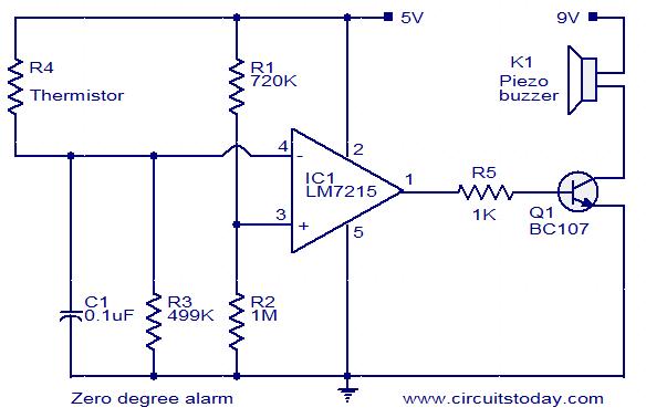
Zero degree Celsius alarm
This circuit is designed to trigger an alarm when the temperature drops below zero degrees Celsius. A thermistor is utilized to measure the temperature. The operational amplifier LM7215 is employed to compare the reference voltage with the voltage from the...
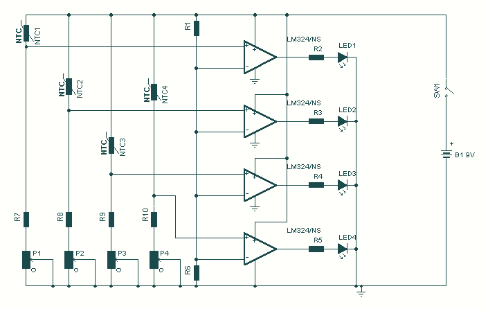
Hot Water Level Indicator
Save fuel bills and the economy of the planet with this circuit. SW1 is a normally open press button switch which allows you to view the level of hot water in a hot water tank. When pressed the voltage difference...
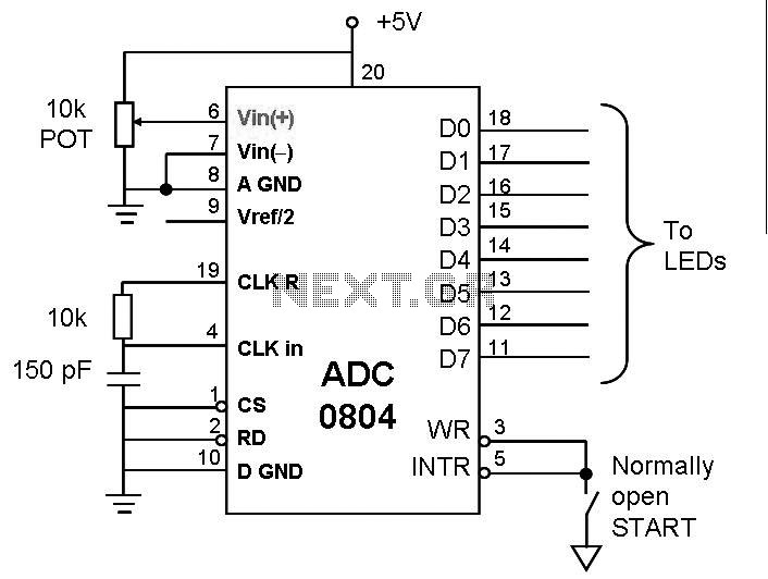
analog to digital converter
This post discusses the interfacing and operation of Analog-to-Digital Converters (ADCs). An ADC is a device that converts the analog signals from transducers into digital signals, enabling computers to process the data. ADCs are essential for obtaining meaningful results when...
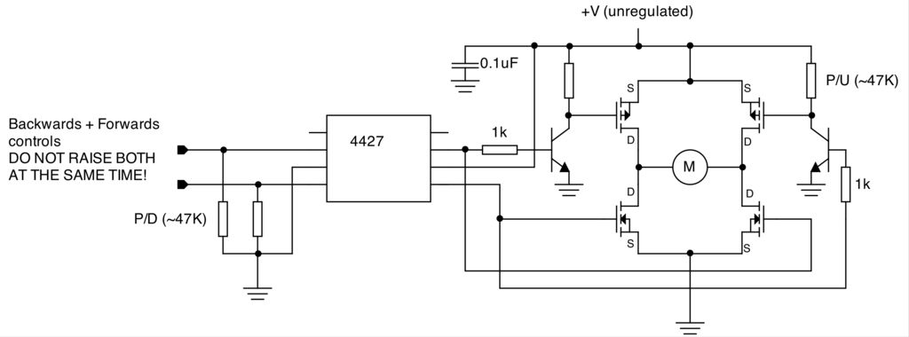
Augmenting a Microcontroller Circuit
To create a versatile and generic microcontroller board, the information provided thus far is sufficient. It covers the essential components needed to achieve this.
The design of a microcontroller board requires careful consideration of various factors to ensure versatility and functionality....
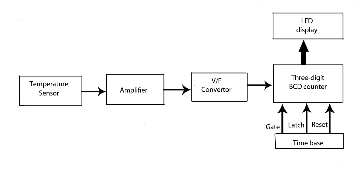
Advanced LED Temperature Indicator
This verified project provides an idea, circuit, and operation of the LED display temperature indicator. It features a digital temperature indicator utilizing a voltage-to-frequency (V/F) converter, along with various electronic projects.
The LED display temperature indicator is designed to provide a...
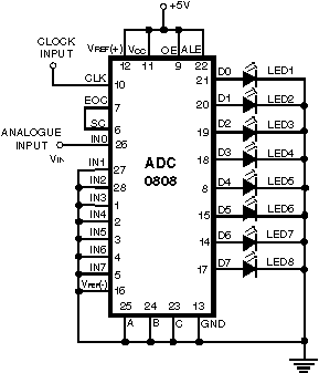
Simple Analog to Digital Converter (ADC)
Normally, an analog-to-digital converter (ADC) requires interfacing through a chip to convert analog signals into digital format. This necessitates both hardware and software, resulting in increased complexity and overall cost. The circuit presented here is configured around the ADC 0808,...
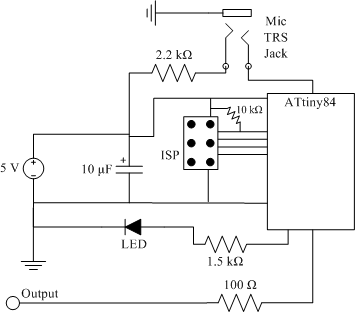
clap sensor construction
The clap sensor is a straightforward circuit that consists of a PC microphone, a microcontroller, and an output. The circuit design features the ATtiny84 microcontroller, chosen for familiarity with the AVR architecture and accessibility to necessary tools. The ATtiny84 is...
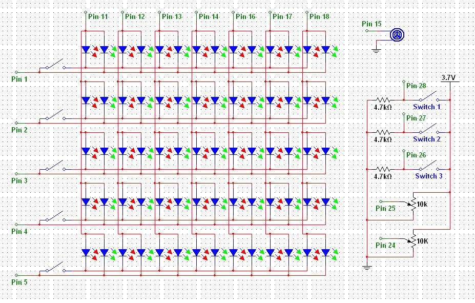
LED Hat Display with Pong using an Arduino
Some time ago, a Pong game was developed as an initial microcontroller project using a 5G-7 LED display, but it was not pursued further. Recently, a hard hat was provided as part of a uniform for an engineering competition, prompting...
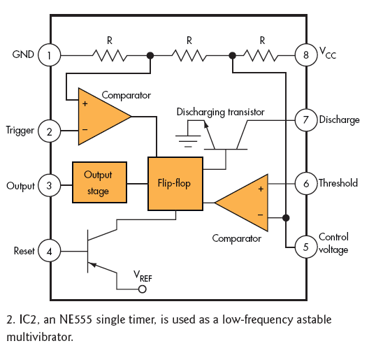
Over-Temperature Alarm Circuit Uses Common Inexpensive Components
Over-Temperature Alarm Circuit Uses Common, Inexpensive Components | Negative-temperature-coefficient (NTC) thermistor, ICs.
The Over-Temperature Alarm Circuit is designed to detect excessive temperatures and provide an alert using readily available and cost-effective components. The core sensing element of this circuit is a...